00197395-03_AI_3D_Sensor-Koplan_X-Serie_S_DE_EN.pdf - 第104页
3 Installation 3.6 Running the cable for the coplanarity computer 104 Assembly Instructions / Montageanleitung SIPLACE X-Series S 3D-Sensor 06/2020 Fig.21: Removing the cable ties ► Remove any existing cable ties (1) . …
3 Installation
3.5 Removing the Station Computer
Assembly Instructions / Montageanleitung SIPLACE X-Series S 3D-Sensor 06/2020 103
3.5 Removing the Station Computer
Up to serial no. Gxxxx:
Fig.18: BoxPC (example of 827C)
► Unplug all connections of the
BoxPC(1)
. If necessary, mark their po-
sitions to make clear assignment easier
later on.
► Lift the BoxPC slightly so that it is re-
leased from the Velcro fixtures.
► Pull it out towards the front.
From serial no. Hxxxx:
Fig.19: BoxPC (example of 627C)
► Unplug all connections of the
BoxPC(1)
. If necessary, mark their po-
sitions to make clear assignment easier
later on.
► Remove the screws fastening the
BoxPC and remove the BoxPC from
the machine.
3.6 Running the cable for the coplanarity computer
Fig.20: Supply door
► Open the supply door (1).

3 Installation
3.6 Running the cable for the coplanarity computer
104 Assembly Instructions / Montageanleitung SIPLACE X-Series S 3D-Sensor 06/2020
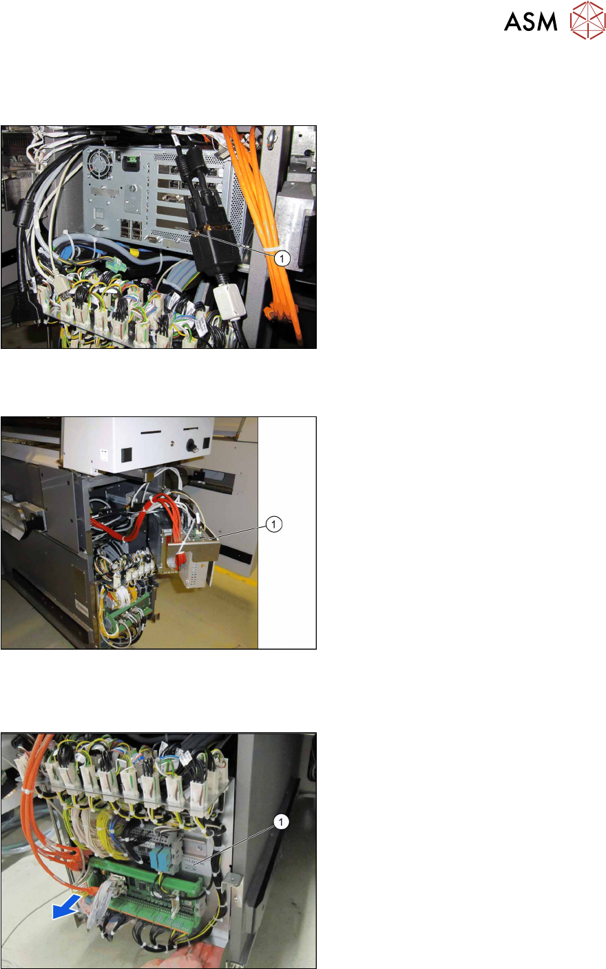
Fig.21: Removing the cable ties
► Remove any existing cable ties (1).
Fig.22: Power cable
Up to serial no. Gxxxx:
► Unplug the present power cable
[03076481‑xx](1)
from the station com-
puter.
► Connect the power cable [03076481-
xx] to the new "Adapter cable power
BoxPC and coplanarity PC" [03090848-
xx](2)
from the set of cables.
The "Adapter cable power BoxPC and co-
planarity PC" [03090848‑xx] is split into two
parts. It merges into a long cable and a short
cable with a connector.
► Plug the short end of the adapter cable
into the station computer.
In the next steps, the long end is run through
the machine and then connected to the co-
planarity computer.
3 Installation
3.6 Running the cable for the coplanarity computer
Assembly Instructions / Montageanleitung SIPLACE X-Series S 3D-Sensor 06/2020 105
Fig.23: CIN box
From serial no. Hxxxx:
► Unplug the present power cable
[03112403‑xx]
from the CIN box.
► Connect the power cable [03112403-
xx] to the new "Adapter cable power
BoxPC and coplanarity PC" [03090848-
xx] from the set of cables.
The "Adapter cable power BoxPC and co-
planarity PC" [03090848‑xx] is split into two
parts. It merges into a long cable and a short
cable with a connector.
► Plug the short end of the adapter cable
into the CIN box.
In the next steps, the long end is run through
the machine and then connected to the co-
planarity computer.
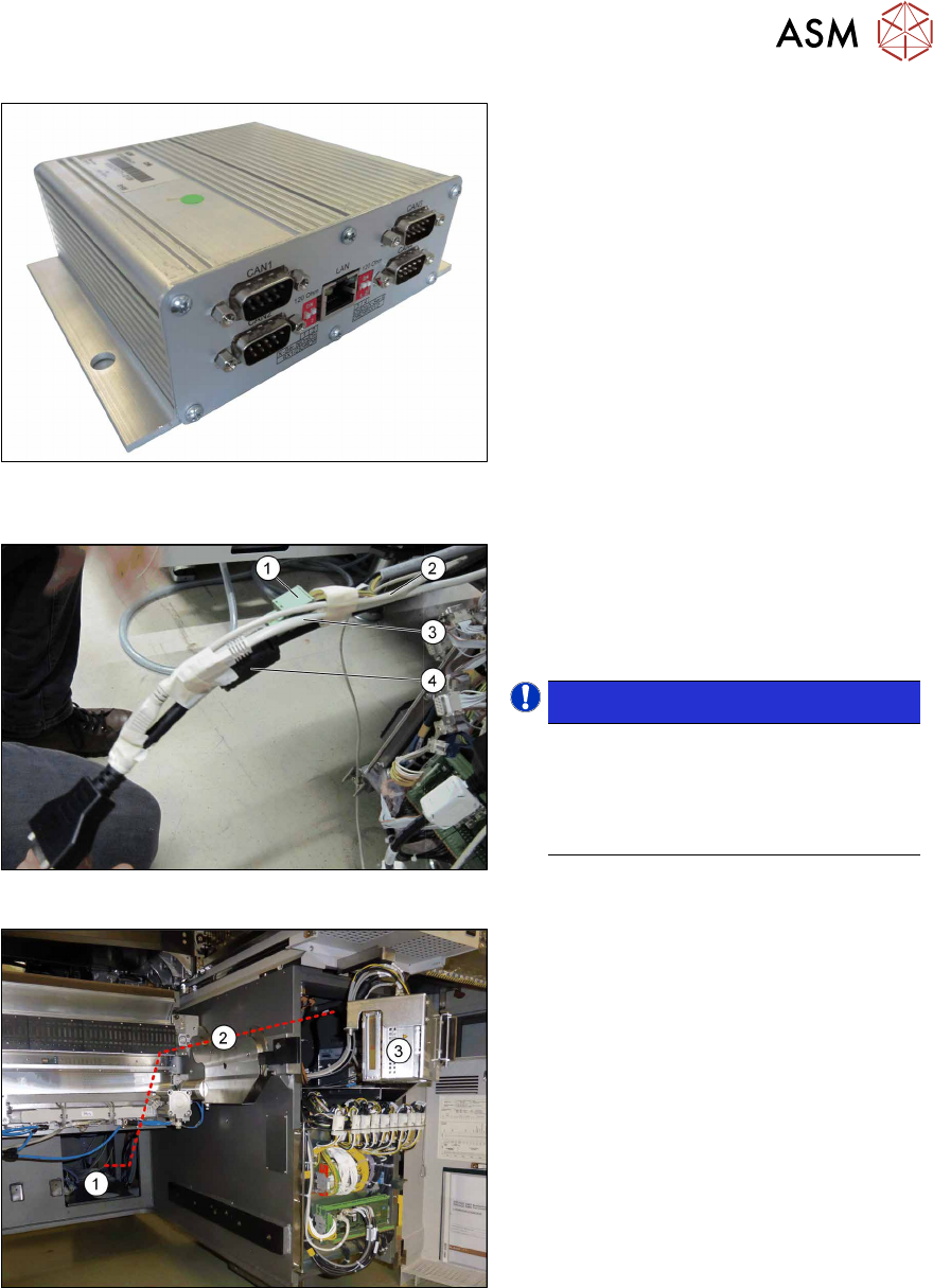
Fig.24: Tying up cables
► Tie up the long end of the adapter
cable "Power BoxPC and coplanarity
PC" (1)
, the DVI extension cable (4),
the patch cable CAT.5e (3)
and the
USB extension cable (2)
.
NOTICE!
The USB cable and the DVI cable are
used only for the installation of the co-
planarity computer.
The LAN cable connects the coplanar-
ity computer to the station computer.
.
Fig.25: Running cables
► Push the four tied up cables from the
station computer(3)
through the
machine frame(2)
to the installation
location(1)
of the coplanarity computer
at location1.