00197395-03_AI_3D_Sensor-Koplan_X-Serie_S_DE_EN.pdf - 第119页
3 Installation 3.12 Installing the Coplanarity Computer Assembly Instructions / Montageanleitung SIPLACE X-Series S 3D-Sensor 06/2020 119 Fig.47: Inserting the interface board (BoxPC 627C shown as example) ► Insert the …
3 Installation
3.12 Installing the Coplanarity Computer
118 Assembly Instructions / Montageanleitung SIPLACE X-Series S 3D-Sensor 06/2020
3.12 Installing the Coplanarity Computer
CAUTION
Highly Sensitive Electrostatic Devices
Observe the instructions in section 1.3.3 "ESD guidelines" [}91].
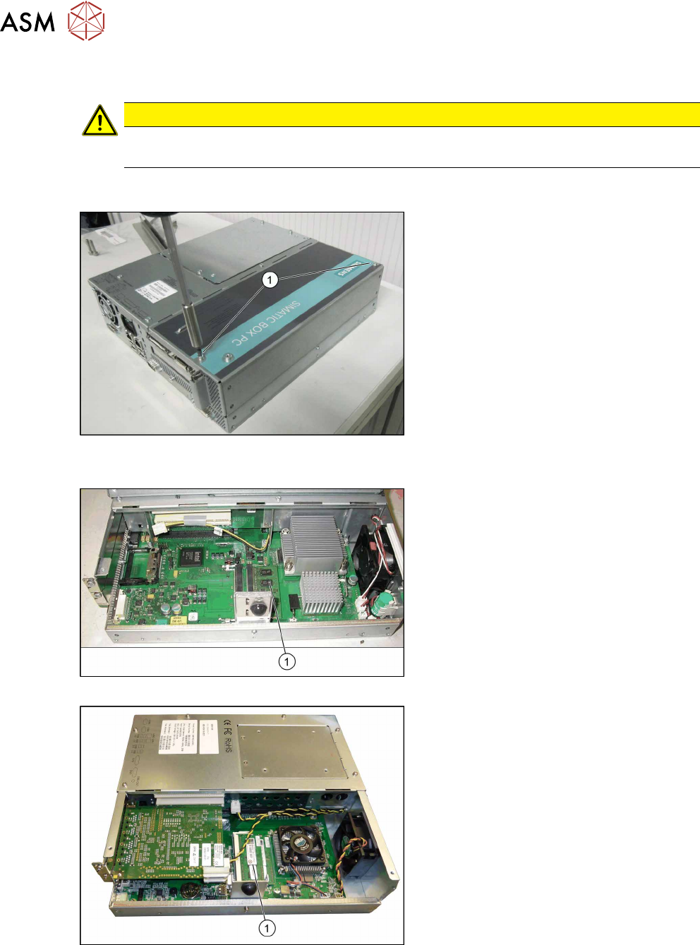
3.12.1 Preparing the Coplan Computer
Fig.44: Removing the cover (BoxPC 627 shown as exam-
ple)
► Remove the screws (1) of the cover on
the coplanarity computer.
► Remove the cover.
Fig.45: Inserting the RAM (BoxPC 627C)
Fig.46: Inserting the RAM (BoxPC ABP402-A iBase)
► Insert the RAM extension "SDRAM
DDR3 PC3-8500 2GB" [03099405-xx]
into the slot(1)
. Make sure that it fits
correctly.
3 Installation
3.12 Installing the Coplanarity Computer
Assembly Instructions / Montageanleitung SIPLACE X-Series S 3D-Sensor 06/2020 119
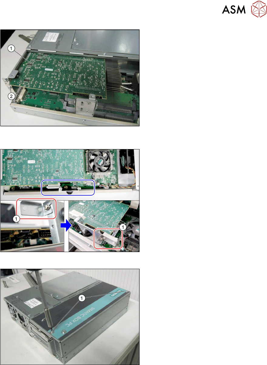
Fig.47: Inserting the interface board (BoxPC 627C shown as
example)
► Insert the new "camera link interface NI
PCI-1428" board [03052591-xx] (1)
into
the slot(2)
. Make sure that it fits cor-
rectly.
Fig.48: Converting the plug-in card support
► iBase BoxPC only: Remove the plug-
in card support(1)
from the left side
and fit to the right side. If you do not do
this, parts on the camera link interface
could be damaged.
Fig.49: Fitting the cover (BoxPC 627C shown as example)
► Close the cover of the coplanarity com-
puter.
► Tighten the screws(1).
3 Installation
3.12 Installing the Coplanarity Computer
120 Assembly Instructions / Montageanleitung SIPLACE X-Series S 3D-Sensor 06/2020
3.12.2 Fixing the Coplan Computer and Routing the Cables
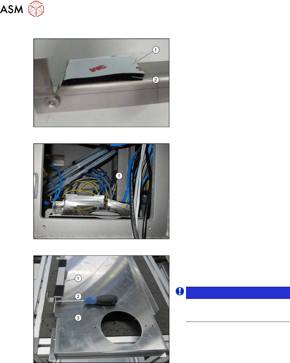
Fig.50: Sticking the Velcro strips into place
► Stick four Velcro strips to the retaining
brackets ,[03102046‑xx] and
[03102026‑xx] with the hard side(2)
fa-
cing down. Leave the protective foil(1)
on the soft side. This is only removed
just before the installation of the co-
planarity computer.
Fig.51: Support plate installed
Support plate (1) inside the machine.
Fig.52: Fixing the retaining bracket
► Fasten the fixture bracket(1) for the co-
planarity computer on the left and right,
using the four M4x6screws (2)
, to the
support plate(3)
at location1.
NOTICE!
Assembly direction:
Make sure that you fit the bracket with
the angle pointing to the left.
.