00197395-03_AI_3D_Sensor-Koplan_X-Serie_S_DE_EN.pdf - 第145页
4 Appendix 4.2 Excerpt from the assembly instructions "SIPLACE X-Series S, SX-Series V3 stationary camera type 25/33 (GigE)" [00197710‑xx] Assembly Instructions / Montageanleitung SIPLACE X-Series S 3D-Sensor 0…
4 Appendix
4.2 Excerpt from the assembly instructions "SIPLACE X-Series S, SX-Series V3 stationary camera type 25/33
(GigE)" [00197710‑xx]
144 Assembly Instructions / Montageanleitung SIPLACE X-Series S 3D-Sensor 06/2020
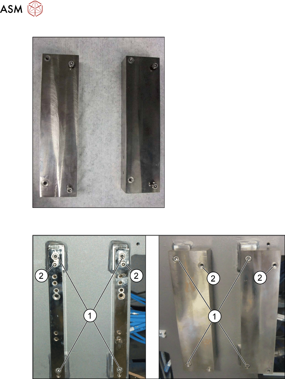
Spacer plates for locations 1 and 4
Fig.103: Spacer plates
Wide spacer plate for locations 1 and 4 with
plug-in screws for fixture to machine frame
Fitting the spacer plates
Fig.104: Left: location 2 and 3; right: location 1 and 4
► Use the screws (M6x45) to fix the spacer plates to the screw fixing points in the machine
frame (1)
. Make sure that the IC label indicates upwards.
► At position (2), tighten the two screws (M6x20) for the camera suspension holder, until the
screw shaft protrudes approx. 15mm above the mount.
4 Appendix
4.2 Excerpt from the assembly instructions "SIPLACE X-Series S, SX-Series V3 stationary camera type 25/33
(GigE)" [00197710‑xx]
Assembly Instructions / Montageanleitung SIPLACE X-Series S 3D-Sensor 06/2020 145
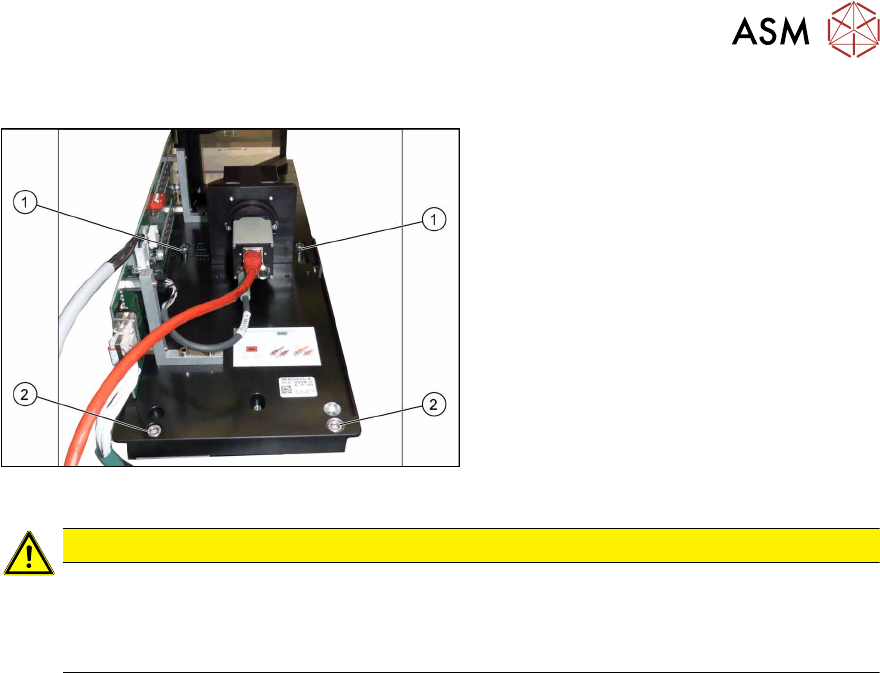
IC Camera Type 33: Fixing the Camera Module
Fig.105: Lower section of camera
► Hook the upper holes (1) on the lower
section of the camera onto the screws
already fitted.
► The camera can only be fitted at one
height. Fix the lower section of the
camera accordingly with the two bot-
tom screws(2).
► Tighten all four screws.
CAUTION
Observe the installation height
After installation, check the installation height. The camera may not protrude over the upper
edge of the conveyor!
Otherwise there is the danger of a crash!
Locations 2 and 3
► If you do not have to install an FC camera at the same location, continue by attaching the
camera cables (see section Connecting the Cable).
► If you also install an FC camera at the same location, proceed with section Fitting the FC
Camera of Type 25 - Location 2 and 3
Locations 1 and 4
► Continue by attaching the camera cables (see section Connecting the Cable).
4 Appendix
4.3 Excerpt from the assembly instructions "SIPLACE X-Series S - stationary camera type
25/33" [00197397‑xx]
146 Assembly Instructions / Montageanleitung SIPLACE X-Series S 3D-Sensor 06/2020
4.3 Excerpt from the assembly instructions "SIPLACE X-
Series S - stationary camera type 25/33" [00197397‑xx]
The following chapter shows excerpts from the assembly instructions. More details can be found in
the assembly instruction manual itself.
4.3.1 Fitting the Camera
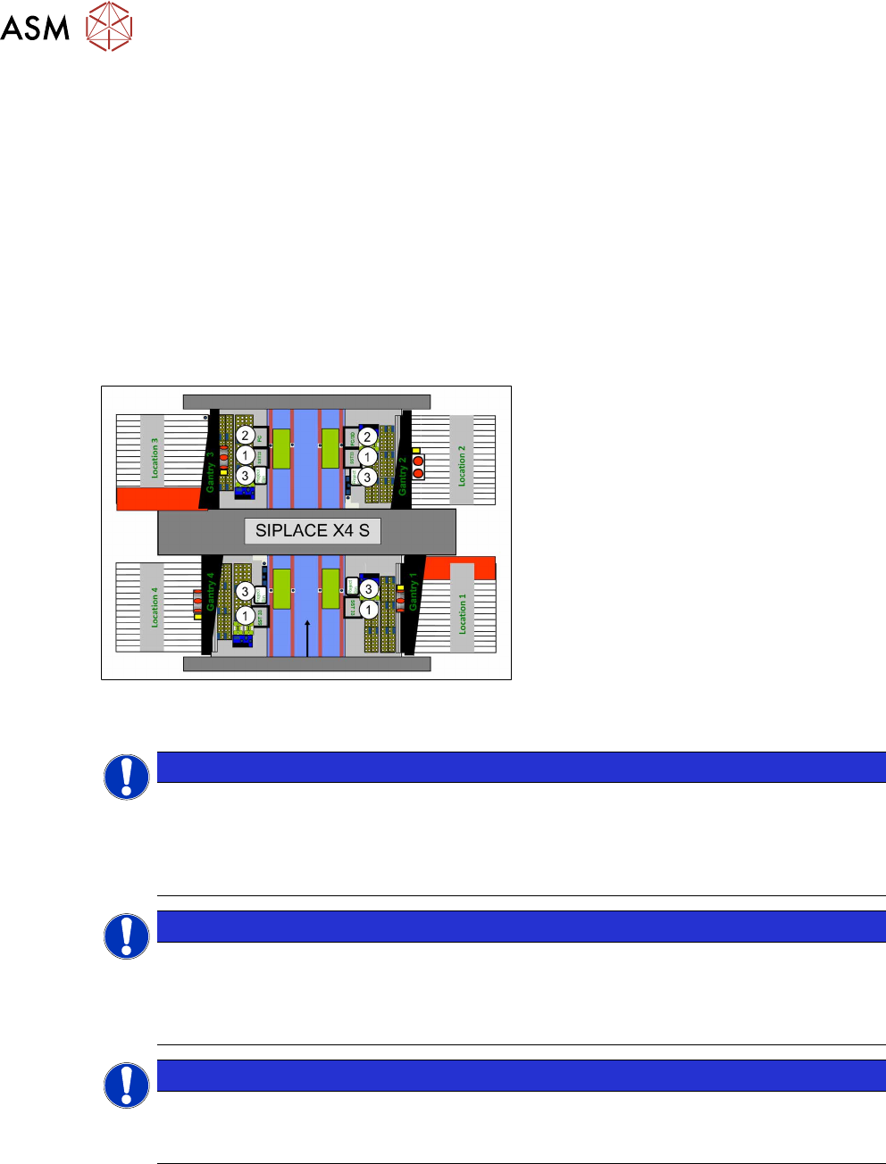
Configurations
IC cameras of type 33 can be installed at all four locations (exception: no installation at PA1 pos-
sible at SIPLACE X4i S).
FC cameras of type 25 can only be installed at locations 2 and 3, only in combination with IC cam-
era type 33.
Fig.106: Installation position of cameras (using example of
SIPLACE X4 S)
1. IC camera, type 33
2. FC camera / 3D coplan (location2
only)
3. Component reject bin
NOTICE
SIPLACE Twin
The FC camera and the 3D coplan module are only possible together with a SIPLACE
Twin. Only one of these options can be fitted at the same location, meaning that either the
FC camera or the 3D coplan module can be used and only in combination with an IC cam-
era.
NOTICE
SIPLACE CPP
► A 3D coplan module can be fitted together with an IC camera and a SIPLACE CPP.
► The combination of an IC camera with a FC camera and a SIPLACE CPP is not pos-
sible.
NOTICE
3D coplan
If a 3D coplanarity is fitted, this only being possible at location 2, the stationary camera (IC
camera) must also be fitted at location 2.