00197395-03_AI_3D_Sensor-Koplan_X-Serie_S_DE_EN.pdf - 第98页
2 Brief Description 2.4 Tools and Equipment Required 98 Assembly Instructions / Montageanleitung SIPLACE X-Series S 3D-Sensor 06/2020 2.3.1 Overview of Parts Fig.10: Overview of parts 1. 3D coplanarity sensor and transm…

2 Brief Description
2.3 Scope of Delivery
Assembly Instructions / Montageanleitung SIPLACE X-Series S 3D-Sensor 06/2020 97
2.3 Scope of Delivery
"3D coplanarity SIPLACE X4 S / X3 S" package [00519807‑xx]:
Quantity Designation Item no.
1 BoxPC ABP402-A CPU1020E 2xPCI SSD W10 (iBase)
(Replaces: control computer BoxPC 627C [03094731‑xx])
03120423-xx
1 3D coplanarity sensor and transmission 03054677-xx
1 Camera link interface NI PCI-1428 03052591-xx
1 3D coplanarity sensor 03052362-xx
1 Cable: camera link 3D sensor (5 meters) 03053017-xx
1 Cable set 3D coplanarity X4 S / X3 S 03091019-xx
1 Adapter cable power BoxPC and coplanarity PC 03090848-xx
1 Cable: power 3D coplanarity sensor 03090849-xx
1 Cable: axis signals 3D sensor 03055217-xx
1 DVI extension cable DVI-D 24+1 2 03103212-xx
1 Patch cable CAT.5e S-FTP l=2m GY 03103204-xx
2 USB extension cable A-St - A-Bu 1.8m 03057639-xx
1 Coplanarity sensor holder assembly 03095549-xx
1 Coplanarity sensor holder 03100624-xx
1 Coplanarity sensor holder at the frame 03100623-xx
3 ISO 4762 - M 6 x 12-A2-70 03042572-xx
2 ISO 4762 - M 5 x 20-A2-70 03042563-xx
1 Assembly kit for BoxPC SX4a 03102011-xx
1 Support sheet right complete PC SX4a 03102046-xx
1 Support sheet left complete PC SX4a 03102026-xx
4 Klettostar loop 20x80 (00348189-xx) 03002842-xx
4 ISO 7380-2 M 4 x 6-A2-70 03099577-xx
1 MS-WIN Embedded Standard 7 system 03096240-xx
1 Assembly materials 3D sensor X-Series S 03104469-xx
1 Calibrating jig, coplanarity module 00315365Sxx
1 Laser label class 2, 50mm 03134118-xx
4 ISO 7379 - 8 x 12-12.9 03005643-xx
2 Self-adhesive mounting base MB3A 19x19mm 00316830-xx
10 Cable ties B = 3.6mm L = 140mm TY 24M 00805141-xx
1 Assembly instructions 3D coplanarity X3 S/X4 S, DE+EN 00197395-xx
1 LAN card PCI-Express 2x Gigabit LAN 03118416-xx
1 Operating system USB package WES7(7xx) V3.3 00117122-xx
2 Brief Description
2.4 Tools and Equipment Required
98 Assembly Instructions / Montageanleitung SIPLACE X-Series S 3D-Sensor 06/2020
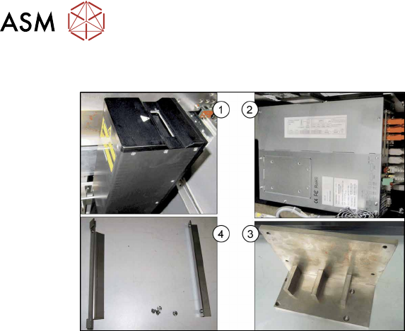
2.3.1 Overview of Parts
Fig.10: Overview of parts
1. 3D coplanarity sensor and transmission
[03054677-xx]
2. BoxPC ABP402-A CPU1020E 2xPCI
SSD (iBase) [03120423‑xx]
(replaces: BoxPC 627C [03094731‑xx])
3. Coplanarity sensor holder
[03100624‑xx]
4. Support sheet right for BoxPC
[03102046‑xx]
Support sheet left for BoxPC
[03102026‑xx]
2.4 Tools and Equipment Required
●
Set of Allen keys
●
Phillips screwdriver
●
Set of Torx spanners
●
Allen key with T-handle 6x300
●
Universal pliers
●
Wire cutters
●
Flashlight
●
Cable tie
●
Installation manual for Windows
You may need additional documents:
●
Assembly instructions "SIPLACE X-Series S, SX-Series V3 stationary camera type 25/33
(GigE)" [00197710‑xx]
●
Assembly instructions "SIPLACE X-Series S - stationary camera type 25/33" [00197397‑xx]
●
Service manual for your machine
2.5 Required Working Time
The complete installation will take approx. 4 hours.

3 Installation
3.1 Preparing the Workplace
Assembly Instructions / Montageanleitung SIPLACE X-Series S 3D-Sensor 06/2020 99
3 Installation
3.1 Preparing the Workplace
► Switch off the machine, disconnect it from the power supply and secure it to prevent unauthor-
ized reactivation. Observe the instructions in section 1.2
"Preparatory work..." [}89].
► Remove the component trolley from locations 1 and 2.
► Remove the used tape chutes at locations 1 and 2 (see 4.1.1 "Replacing the waste tape
slide" [}137]).
See also
2 4.2.1 "Fitting the Camera" [}140]
3.2 Preparing the Installation of the IC Camera (Type 33)
NOTICE
3D coplanarity module and stationary camera
IC cameras of type 33 can only be fitted next to the 3D coplanarity module at location 2.
On a SIPLACE X2S / X3S the stationary camera is fitted at location 3. If a 3D coplanarity
module is fitted, the stationary camera must be fitted/refitted at location 2.
Perform the following tasks and refer to the appropriate assembly instructions (see below):
► Refit the stationary camera from location 3 to location 2.
► Set the DIP switch to location 2.
► Connect CAN2 to the component camera.
► Connect GigE 3 to the component camera.
Refer also to the appropriate assembly instructions:
●
Assembly instructions "SIPLACE X-Series S, SX-Series V3 stationary camera type 25/33
(GigE)" [00197710‑xx]
●
Assembly instructions "SIPLACE X-Series S - stationary camera type 25/33" [00197397‑xx]
Excerpts from these assembly manuals can be found in the annex:
●
4.2 "Excerpt from the assembly instructions "SIPLACE X-Series S, SX-Series V3 stationary
camera type 25/33 (GigE)" [00197710‑xx]" [}140]
●
4.3 "Excerpt from the assembly instructions "SIPLACE X-Series S - stationary camera type
25/33" [00197397‑xx]" [}146]