00197395-03_AI_3D_Sensor-Koplan_X-Serie_S_DE_EN.pdf - 第151页
4 Appendix 4.3 Excerpt from the assembly instructions "SIPLACE X-Series S - stationary camera type 25/33" [00197397‑xx] Assembly Instructions / Montageanleitung SIPLACE X-Series S 3D-Sensor 06/2020 151 Spacer p…
4 Appendix
4.3 Excerpt from the assembly instructions "SIPLACE X-Series S - stationary camera type
25/33" [00197397‑xx]
150 Assembly Instructions / Montageanleitung SIPLACE X-Series S 3D-Sensor 06/2020
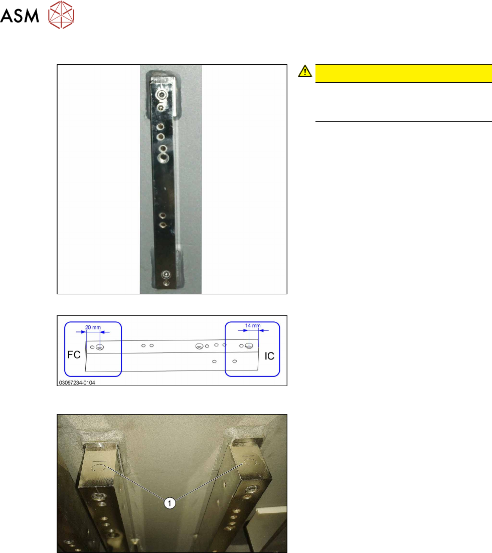
Spacer plates for locations 2 and 3
Fig.112: Narrow spacer plates for locations 2 and 3
Fig.113: Correct labeling of spacer plates
CAUTION!
Incorrect labeling
In a few cases, these spacer plates
are supplied with incorrect labeling.
.
► Compare your spacer plates with the
diagram.
If the label does not match the diagram,
correct the label.
– FC: This side must be on top for FC
cameras and Q10 magazines
(Smart Pin Support).
– IC: This side must be on top for IC
cameras.
Fig.114: IC top
IC and FC are marked on the top and bot-
tom of the spacer plates.
When fitting an IC camera, make sure that
the IC lettering (1)
faces upwards.
4 Appendix
4.3 Excerpt from the assembly instructions "SIPLACE X-Series S - stationary camera type
25/33" [00197397‑xx]
Assembly Instructions / Montageanleitung SIPLACE X-Series S 3D-Sensor 06/2020 151
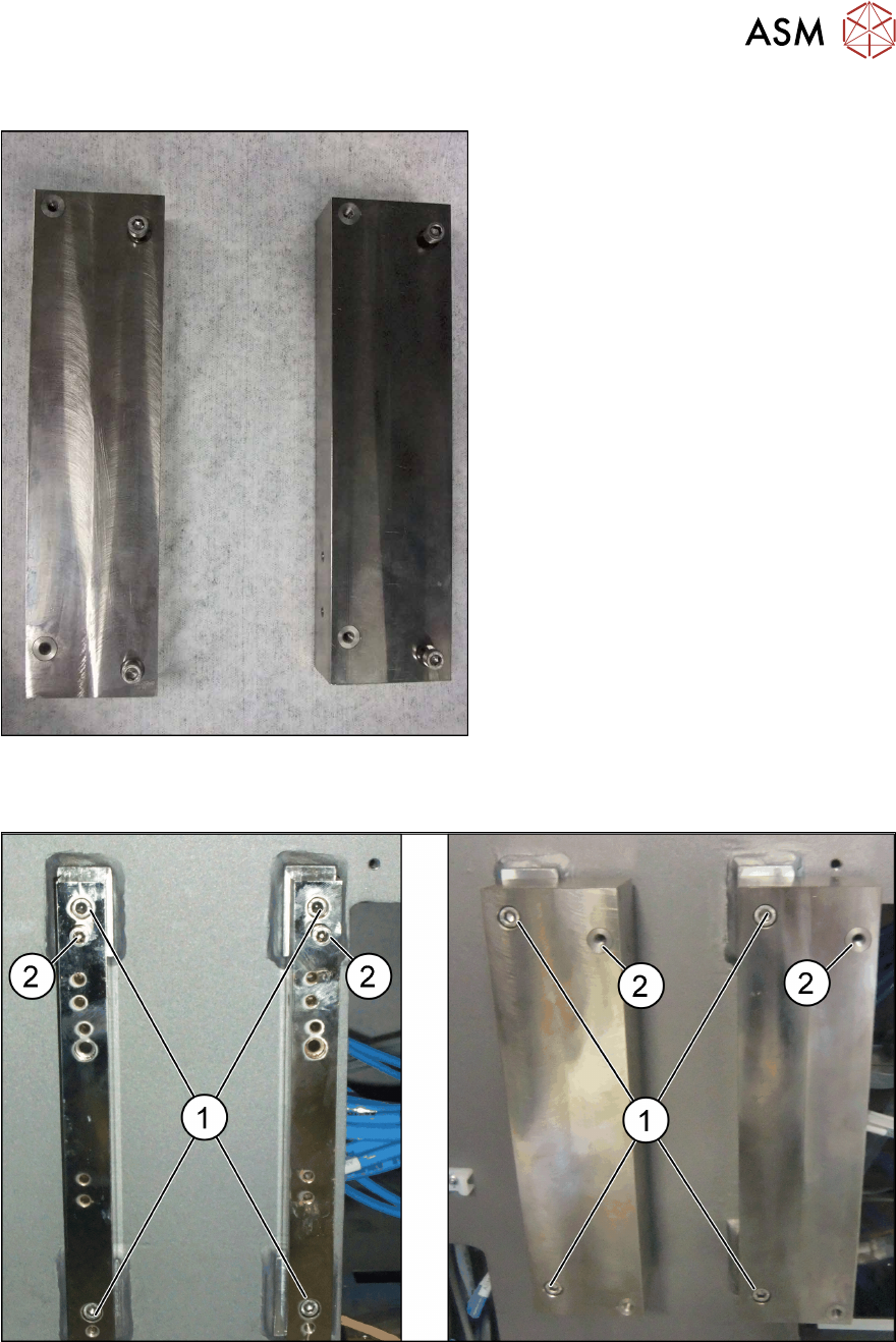
Spacer plates for locations 1 and 4
Fig.115: Spacer plates
Wide spacer plate for locations 1 and 4 with
plug-in screws for fixture to machine frame
Fitting the spacer plates
Fig.116: Left: location 2 and 3; right: location 1 and 4
► Use the screws (M6x45) to fix the spacer plates to the screw fixing points in the machine
frame (1)
. Make sure that the IC label indicates upwards.
► At position (2), tighten the two screws (M6x20) for the camera suspension holder, until the
screw shaft protrudes approx. 15mm above the mount.
4 Appendix
4.3 Excerpt from the assembly instructions "SIPLACE X-Series S - stationary camera type
25/33" [00197397‑xx]
152 Assembly Instructions / Montageanleitung SIPLACE X-Series S 3D-Sensor 06/2020
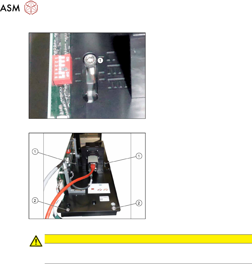
IC Camera Type 33: Fixing the Camera Module
Fig.117: Markings for different installation heights (1)
► Hook the camera on its screws onto the
spacer plates.
Fig.118: Lower section of camera
► Hook the upper holes (1) on the lower
section of the camera onto these two
screws. (Key hole principle for cameras
of type 33 from version 06.)
► Use the two lower screws (2) to adjust
the lower section of the camera to the
correct installation height at position I
(1)
and tighten all four screws.
CAUTION
Observe the installation height
When fitting the camera, observe the correct installation height. Otherwise there is the
danger of a crash!
Locations 2 and 3
► If you do not have to install an FC camera at the same location, continue by attaching the
camera cables (see section Electrical connections).
► If you need to install an FC camera at the same location, continue with section Fitting the FC
Camera of Type 25 - Location 2 and 3
Locations 1 and 4
► Continue by attaching the camera cables (see section Electrical connections).