CP7 Series Level3 Tutorial Manual.pdf - 第101页
Resolution: 0.002 mm/pulse World (Zero) Affected Calibration data: NC Origin Pos. → MC0ZOVNC 5.1.1 Removing the NC-Axis Motor Procedure: 1. Turn OFF the machine power. 2. Disconnect both electrical connections to the mot…
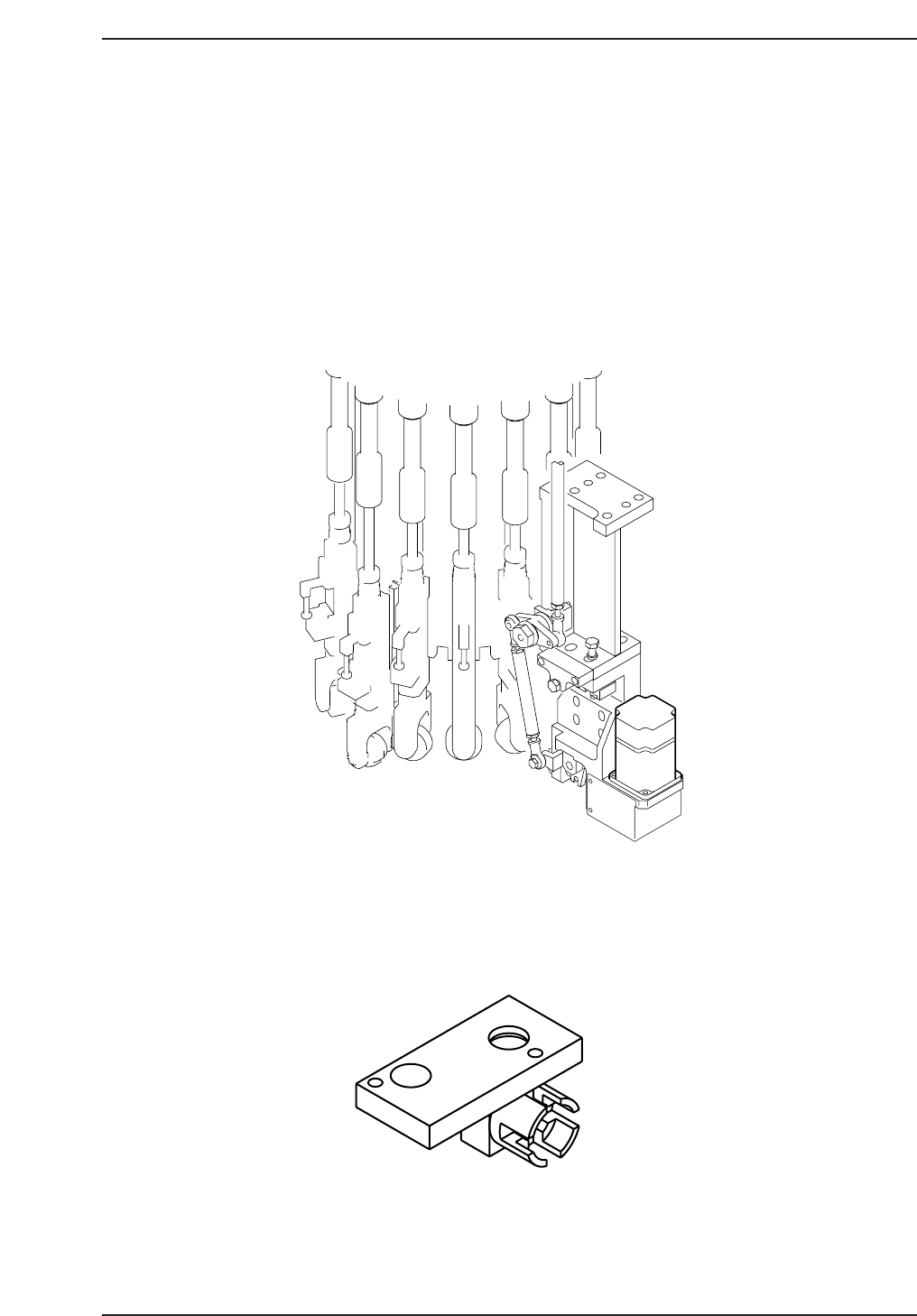
5.1 Replacing the NC-Motor
The NC motor is responsible for changing the nozzle size on each of the machine’s
placing heads. Nozzle change is only performed if the next pickup operation
requires a different sized nozzle.
Any failure of the NC-motor and nozzle holder clutches to align will result in
various NC related problems. NC-motor adjustments should be carried out in the
following situations.
- After replacement of the NC-motor.
- After replacement of the NC tension belt
Required Tools: 1 Set of Allen Wrenches
1 Phillips Screwdriver
Required Jig: Nozzle Axis Alignment Jig
ADCPJ8040
CP7T35002
NC Motor
CP7T35001
Chapter 5 5.1 Replacing the NC-Motor
Edition 2.0 5-1 CP-7-series Level 3 Tutorial

Resolution: 0.002 mm/pulse World (Zero)
Affected Calibration data: NC Origin Pos. → MC0ZOVNC
5.1.1 Removing the NC-Axis Motor
Procedure:
1. Turn OFF the machine power.
2. Disconnect both electrical connections to the motor.
3. Remove the four (4) allen bolts securing the motor to the mounting
bracket and carefully remove.
4. Separate the gear from the motor by loosening the set screw and remove.
Caution
Ensure that a back-up of Proper data is taken prior to replacing the
motor.
CN001
Chapter 5 5.1 Replacing the NC-Motor
Edition 2.0 5-2 CP-7-series Level 3 Tutorial
5.1.2 Installing the NC-Axis Motor
Procedure:
1. Reattach the gear to the motor and secure the new motor to the machine
with the two (2) mounting bolts.
2. Reconnect the two electrical connectors to the motor.
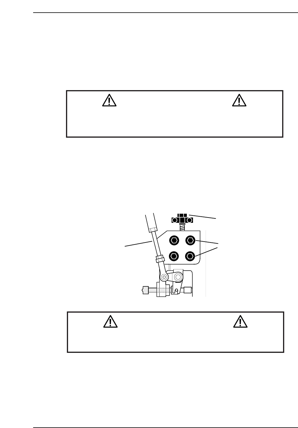
5.1.3 Nozzle Changer Alignment
Procedure:
1. Remove the adjustment rod from the lower part of the cam box.
(or alternatively, cut the air supply).
2. Move placing shaft A to 200° at station 14 and install the alignment jig.
3. Loosen the four (4) positioning bolts and lower or raise the bracket using
the adjustment bolts until the nozzle changer clutch slides smoothly into
the jig socket.
Caution
As the alignment jig spans two nozzle shafts, do not move the cam-axis
while the jig is attached.
CN005
Remove Adjustment
Rod
Adjustment
Bolt
Positioning
Bolts
CP7T35003
Notice
Note that as the CP-7 utilizes absolute encoders on all axes, it is no
longer necessary to boot up the machine in Mechacheck mode when
performing motor adjustments.
N001
Chapter 5 5.1 Replacing the NC-Motor
Edition 2.0 5-3 CP-7-series Level 3 Tutorial