CP7 Series Level3 Tutorial Manual.pdf - 第63页
2.2.3 Measuring ZL_IN, ZL_OUT Procedure: 1. Adjust the conveyor width to hold a 356 x 254 mm board (or similarly large board). CP-742E(ME): 457 x 356 mm 2. Load the board onto the main conveyor, then move the OUT-carrier…
2.2.2 Measuring XL_IN, XL_OUT
Procedure:
1. Move the OUT-carrier to the advance limit positions.
2. Manually inch the XY-table to YL_OUT in the Y direction and to the -
11250 pulse position in the X direction.
3. Press the EMERGENCY STOP button, then ensuring that both the main
conveyor clamper and the OUT carrier clamper are both closed, raise the
Z-axis to approximately 15000 pulses (CP-742E(ME): 23100). At this
point, the clamper claws and the carrier claws should be engaged. If not,
raise the Z-axis accordingly.
4. Using the motor coupling, manually move the X-axis carefully until the
carrier claws on the front carrier are perfectly aligned with the claws on
the reference clamper. Record the motor pulse count.
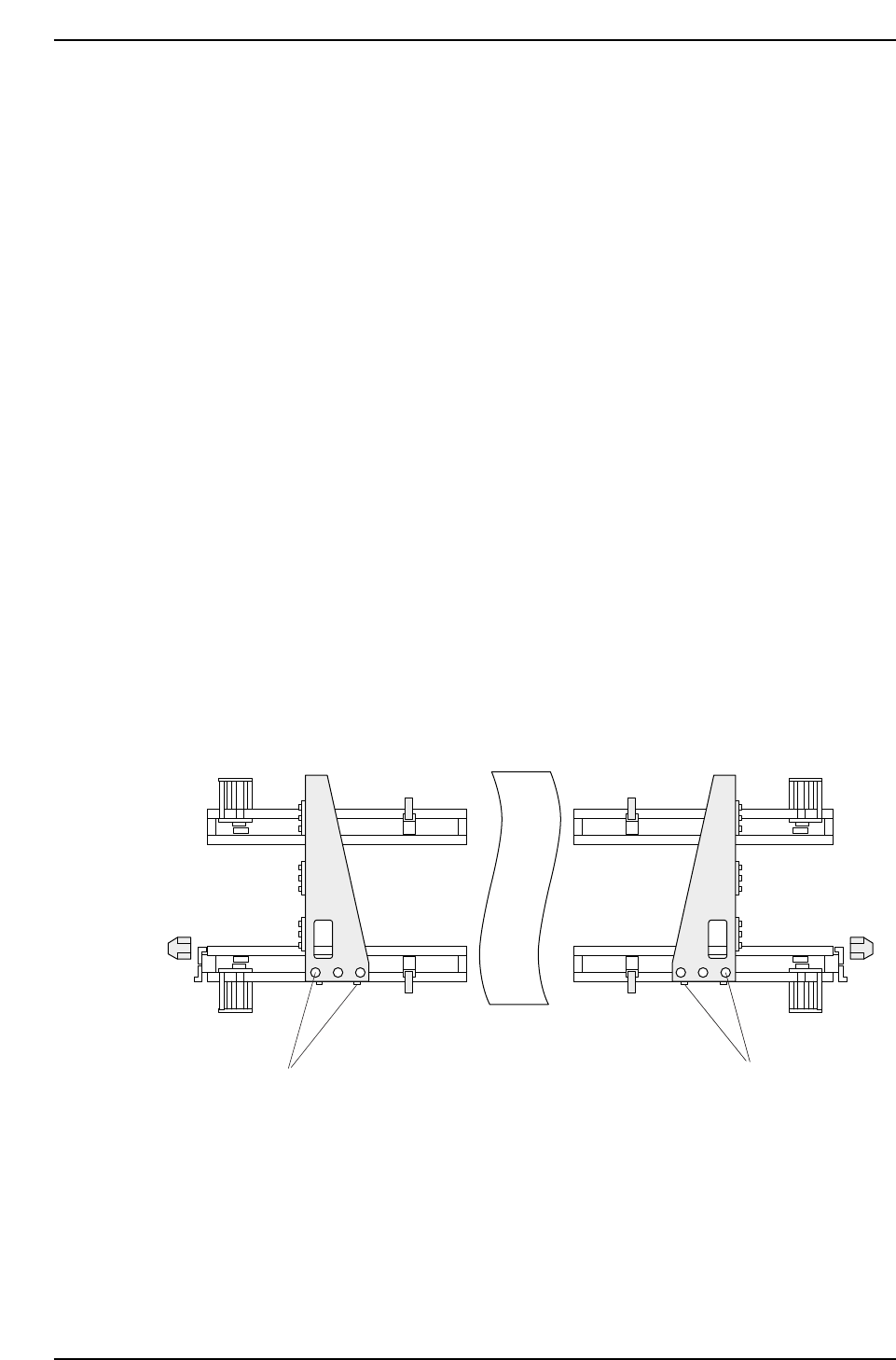
5. To align the claws on the rear side, loosen all five (5) bolts on the carrier
bracket (see figure below) and slide the bracket from left to right until in
position. Finally, tighten the bolts carefully.
6. Repeat the process for XL_IN, moving the Y-axis to YL_IN and the X-axis
to the - 220500 pulse position (CP-742E(ME): -271000).
7. Record XL loading position values in calibration data using the
following commands:
[MAINTENANCE] → [CALIBRATION] → [LOADING POS]
Adjustment bolts(5)
Adjustment bolts(5)
CP7T32006
Chapter 2 2.2 Loading Position Adjustments
Edition 2.0 2-6 CP-7-series Level 3 Tutorial

2.2.3 Measuring ZL_IN, ZL_OUT
Procedure:
1. Adjust the conveyor width to hold a 356 x 254 mm board (or similarly
large board). CP-742E(ME): 457 x 356 mm
2. Load the board onto the main conveyor, then move the OUT-carrier to
the advance limit position.
3. Inch the Y-axis to the YL_OUT position and the X-axis to the XL_OUT
position.
4. Using the I/O, open the out carrier [MAINTENANCE] - [I/O CHECK] -
[STANDARD] - [Y083 OUT-CARRIER OPEN], and the main lifter
clamper [Y044 MAIN-LIFTER UNCLAMP].
5. Manually raise the Z-axis to the 16250 pulse position (CP-742E(ME):
23100 pulses) and then using the I/O, close the out carrier [Y082 OUT-
CARRIER CLOSE]. Raise the Z-axis higher if the carrier fails to fully
clamp the board. Lower the Z-axis until there is no contact with the OUT
carrier.
6. Attach a dial gauge to the surface of the board, as close to the rear carrier
as possible, then set the dial to zero. Slowly raise the Z-axis until the
main lifter comes into contact with the OUT carrier and the dial gauge
displays 0.5 mm. Note the motor pulse count at this point. Repeat this
step for the front carrier and again note the motor pulse count.
7. The larger of the two noted values is ZL_OUT.
8. Repeat the procedure for ZL_IN.
9. Verify that both loading position sensors are triggered when the table is
in it’s respective position.
10. Record both positions in calibration data using the following commsnds:
[MAINTENANCE] → [CALIBRATION] → [LOADING POS]
Note: +OT adjustment should be performed now that the ZL position has been ascertained.
Chapter 2 2.2 Loading Position Adjustments
Edition 2.0 2-7 CP-7-series Level 3 Tutorial
2.2.4 Loading Position Sensor Adjustment
Procedure:
1. Adjust the bracket so that the sensor beam is centered directly over the
reflective silver area of the sensor dog.
2. Ensure that there is a space of 11.5 mm between the sensor and the dog.
3. Confirm the sensor reaction at the I/O, XOBF XY-Table Inside Loading
Position Check, X0DA XY-Table Outside Loading Position Check.
4. Move the table to the respective loading position and inch 250 motor
pulse counts in the plus and minus X and Y directions. Note the four
values displayed on the sensor amplifier at each of theses points and set
the highest one as the amplifier sensitivity threshold level.
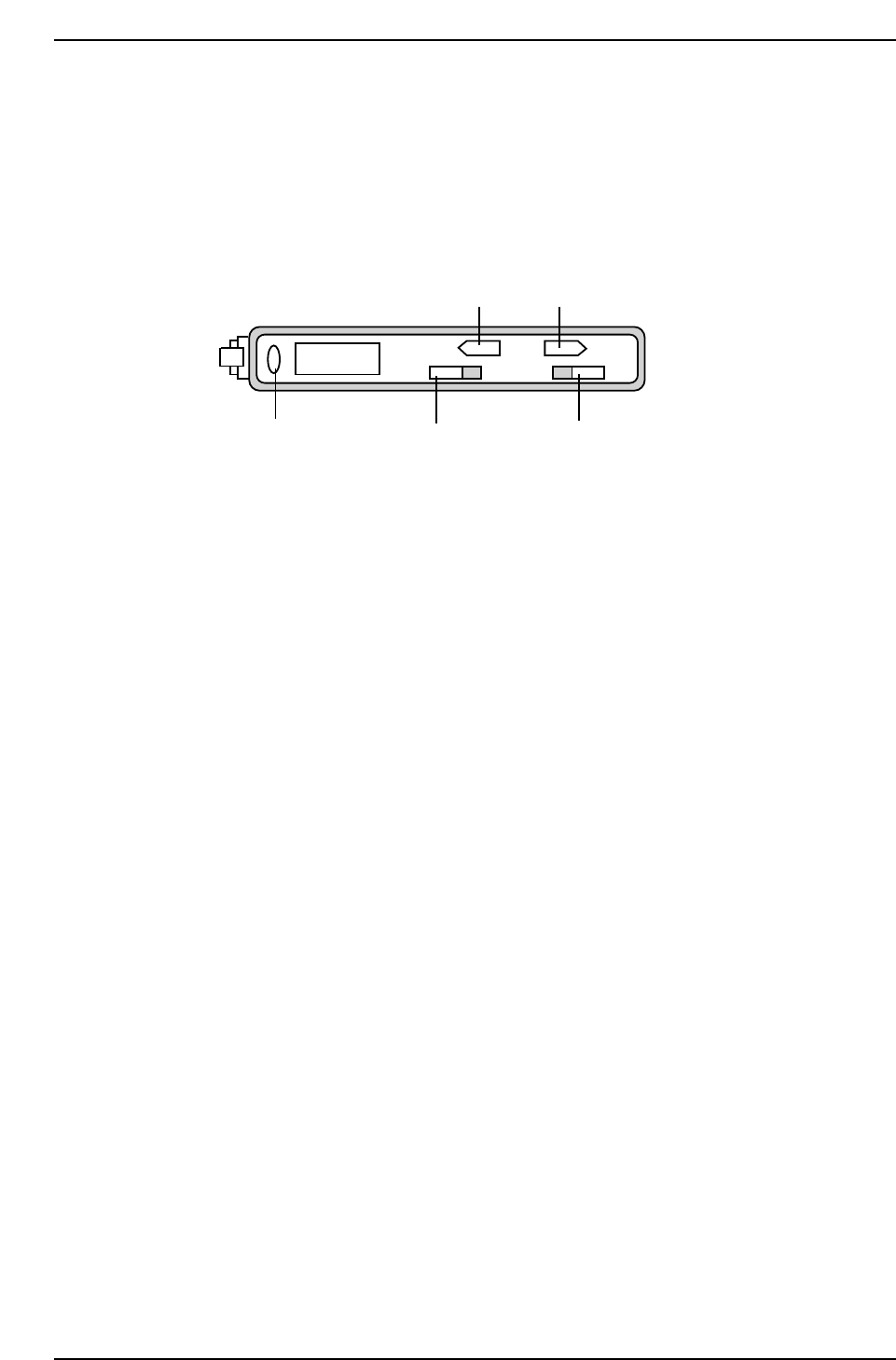
5. To adjust the amplifier, move back to the loading position once more,
ensure that switch 1 is set to “L”(light ON), and then set switch 2 to
“ADJ”.
6. Use the up and down buttons (3 and 4) to adjust the amplifier reading to
the previously noted threshold value and return switch 2 to “RUN”.
7. Inch away from loading position then move back to confirm that the
LED (5) comes on.
ADJ MODE
RUN DLSET
TEACH
2504
1
2
34
5
CP7T32007
Chapter 2 2.2 Loading Position Adjustments
Edition 2.0 2-8 CP-7-series Level 3 Tutorial