CP7 Series Level3 Tutorial Manual.pdf - 第113页
6.2 NZ-Axis Adjustments Procedure: 1 . Loosen the NZ-axis motor coupling and push it against the minus mechanical stopper. 2 . Manually rotate the motor until the counter value reads zero, then tighten the coupling (torq…

Notes:
Chapter 6 6.1 Replacing the NZ-Motor
Edition 2.0 6-4 CP-7-series Level 3 Tutorial
6.2 NZ-Axis Adjustments
Procedure:
1. Loosen the NZ-axis motor coupling and push it against the minus
mechanical stopper.
2. Manually rotate the motor until the counter value reads zero, then
tighten the coupling (torque: 0.8 Nm).
3. Pull the axis against the minus mechanical stopper and ensure the motor
position is 0 ± 50 pulses. Move the axis 100 pulses away from the
stopper position and set this in calibration data using the following
commands:
[MAINTENANCE] → [CALIBRATION] → [TRAVEL LIMITS] →
[MINIMUM LIMIT NZ].
4. Pus the axis against the plus mechanical stopper and ensure that the
motor position is 12770 ± 500. Move 100 pulses back from this position
and set this in calibration data using the following commands:
[MAINTENANCE] → [CALIBRATION] → [TRAVEL LIMITS] →
[MAXIMUM LIMIT NZ].
5. Rotate the cam angle to zero and activate the pickup solenoid using the
I/O: Y031 ST1 PICKUP SOL ENGAGED.
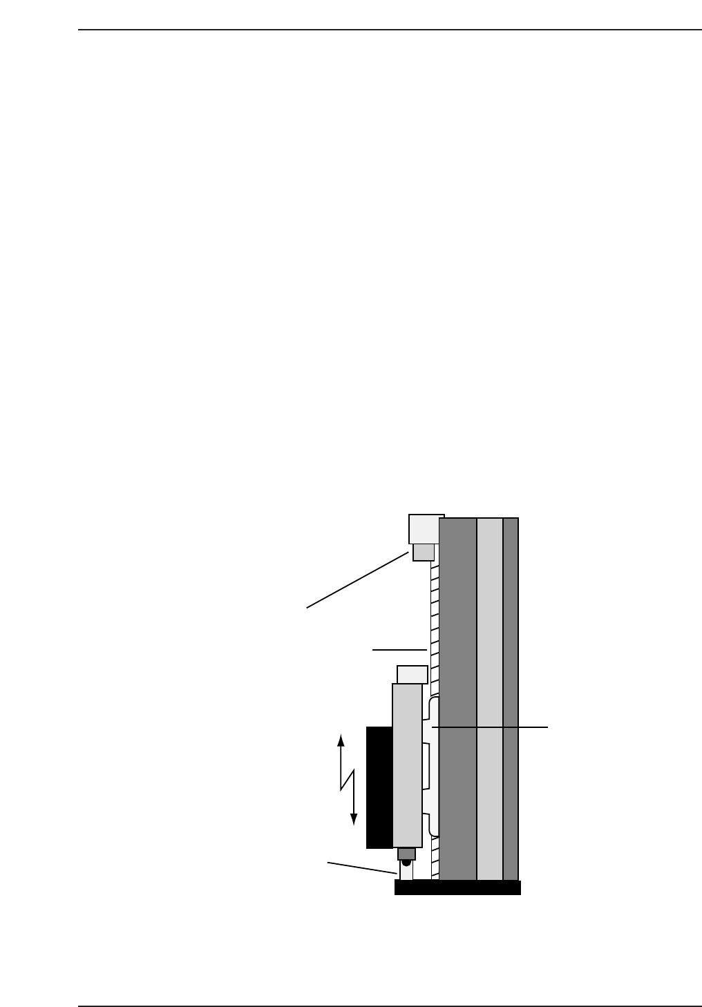
Ballscrew
Plus mechanical
stopper
Minus mechanical
stopper
Linear-
guide
CP7T36004
Chapter 6 6.2 NZ-Axis Adjustments
Edition 2.0 6-5 CP-7-series Level 3 Tutorial
6. Set the pickup height jig to zero, and remove the stopper bracket. Then
slot the jig onto the device table (slot no. 23) and install the nozzle jig on
the nozzle holder (no. 1).
7. Rotate the cam axis to 170°, ensuring that the needle of the pickup height
jig is directly below the nozzle jig.
8. Manually move the NZ-axis until the dial gauge reads zero (at this point
there should be a space of 0.65 mm between the tip of the nozzle and the
feeder). Take note of the motor pulse count at this point.
9. Repeat the procedure for all 16 heads. Take the average value of the 16
heads and set this as the NZ origin position in the machine’s calibration
data using the following commands:
[MAINTENANCE] → [CALIBRATION] → [PICKUP REFERENCE] →
[NZ ORIGIN POSITION].
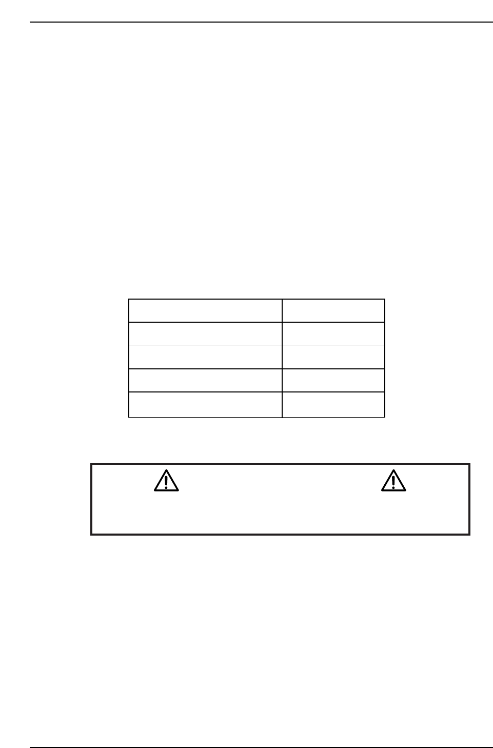
CP-732E Calibration Data Servo Count Chart (NZ-axis)
Caution
Ensure that new Calibration data is backed-up to the host computer
once the adjustment procedure is complete.
CN002
Plus mechanical stopper
Max limit pos.NZ
Pickup Pos. NZ
Min limit pos. NZ
Minus mechanical stopper
12770 ± 500
12670 ± 500
4000 ± 1000
100 ± 50
0 ± 50
CP7T36005
Chapter 6 6.2 NZ-Axis Adjustments
Edition 2.0 6-6 CP-7-series Level 3 Tutorial