CP7 Series Level3 Tutorial Manual.pdf - 第122页
7.2 Mark Camera Adjustments 7.2.1 Focus Adjustment Procedure: 1. Set the switch at the rear of the amplifier as shown in the diagram below. 2. Attach the tooling pin jig to the reference side of the main conveyor, and th…

7.1.2 Mark Camera Installation
Procedure:
1. Use a small amount of glue (Loctite 425) when reattaching the aluminum
housing to the camera unit, and tighten using a torque wrench (torque:
4–5 Nm).
2. Reattach the camera unit with the four (4) module mounting bolts and
reconnect the video cable to the power supply.
Chapter 7 7.1 The Mark Camera
Edition 2.0 7-4 CP-7-series Level 3 Tutorial
7.2 Mark Camera Adjustments
7.2.1 Focus Adjustment
Procedure:
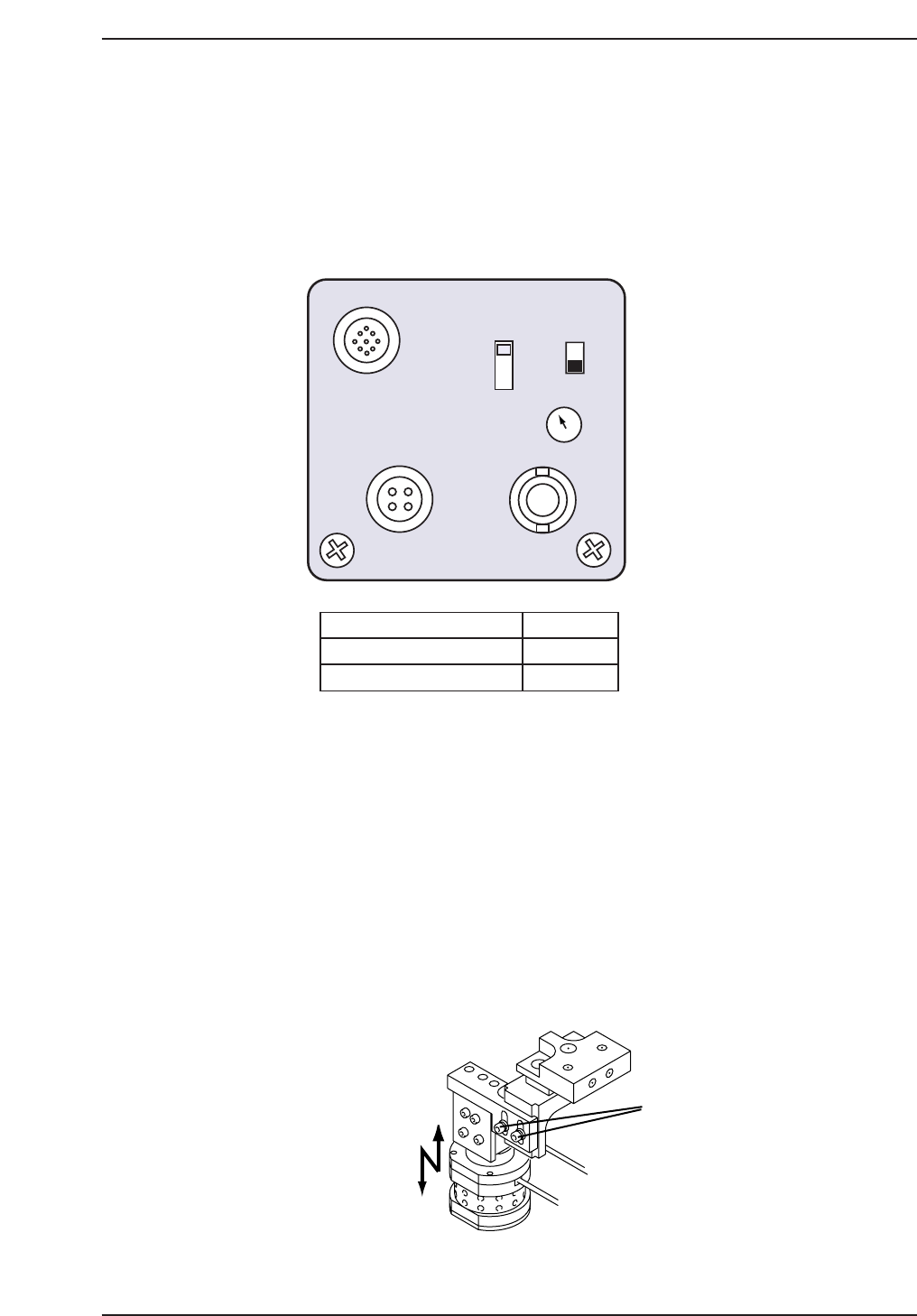
1. Set the switch at the rear of the amplifier as shown in the diagram below.
2. Attach the tooling pin jig to the reference side of the main conveyor, and
then clamp the fiducial jig plate on the conveyor, adjusting the movable
pin on the tooling pin jig appropriately.
3. Move the fiducial jig plate to the read position using the following
commands:
[MAINTENANCE] → [CALIBRATION] → [MARK CAMERA
RESOLUTION] → [MOVE] → START.
The X, Y and Z-axes will now move to their respective read positions.
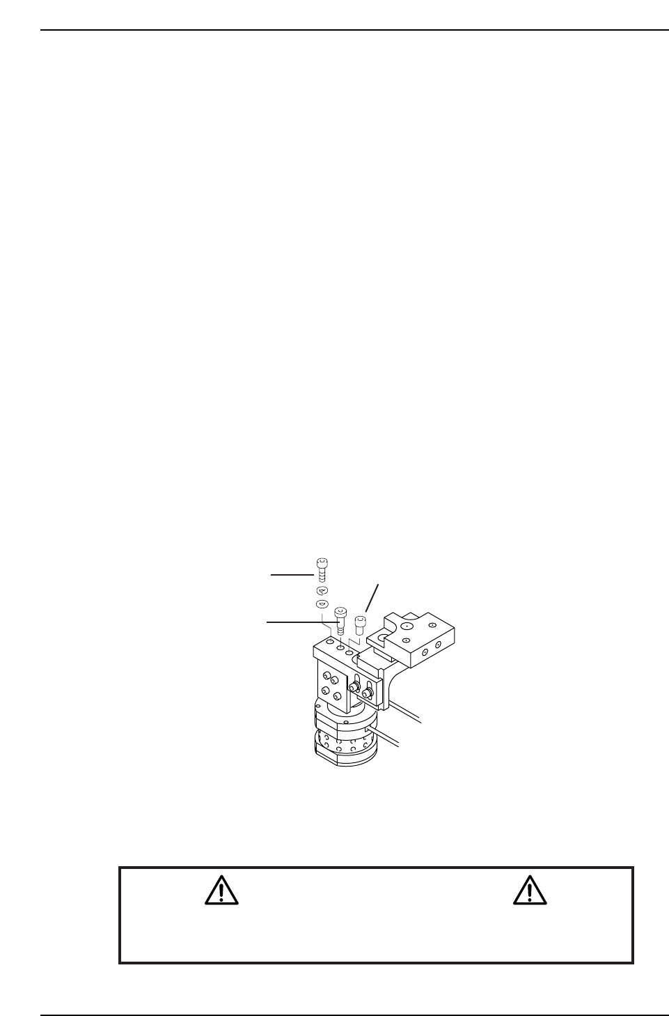
4. Loosen the two (2) adjustment bolts as shown on the following page, and
adjust the height to improve the focus.
Loosen
CP7T37006
1/30N
1/60N
1/30I
DC IN/SYNC
DC IN12V
SHUTTER
VIDEO
ON
OFF
SELECT
GAIN
SELECT SWITCH
GAIN SWITCH
SHUTTER SWITCH
1/30N
OFF
F
F
CP7T37005
Chapter 7 7.2 Mark Camera Adjustments
Edition 2.0 7-5 CP-7-series Level 3 Tutorial
7.2.2 Mark Camera Resolution, Skew, and Xc Yc
Calibration
Procedure:
1. Move each axis to its respective read position using the following
commands:
[MAINTENANCE] → [CALIBRATION] → [MARK CAMERA
RESOLUTION] → [MOVE] → START.
2. Inch the XY-table to align the black center mark on the jig with the cross
hairs on the monitor. Execute the following commands to
simultaneously measure camera resolution, mark read position (Xc Yc),
and camera skew:
[MEASURE] → START.
3. Ensure that the values for camera resolution lie within the following
range:
X: 17.92 ~ 19.81 um/Pixel
Y: 18.02 ~ 19.91 um/Pixel
If outside the prescribed range, loosen the focus adjustment bolts and
adjust the height of the camera. Remeasure the resolution. Repeat until
the value falls within range.
4. To adjust the camera angle, loosen the fixing bolt holding the camera in
position. Rotate the adjustment bolt while remeasuring until the value
for Delta Q comes to zero (Tolerance = 0 ± 0.05°).
Note: On the CP-742E(ME), the location of the pivot and eccentric bolt are reversed.
5. Once the value for Delta Q is within tolerance levels, tighten the fixing
bolt and remeasure.
Caution
Ensure that new calibration data is backed-up to the host computer once
the adjustment procedure is complete.
CN002
Fixing bolt
Pivot
Eccentric bolt
CP7T37007
Chapter 7 7.2 Mark Camera Adjustments
Edition 2.0 7-6 CP-7-series Level 3 Tutorial