CP7 Series Level3 Tutorial Manual.pdf - 第131页
8.2 Parts Camera Adjustments 8.2.1 Focus Adjustment Procedure: 1. With the cam at “200°”, open the vacuum spool for the nozzle at Station 5, and place a small leaded (or nozzle jig) part on the nozzle tip. 2. To display …
8.1.2 Parts Camera Installation
Procedure:
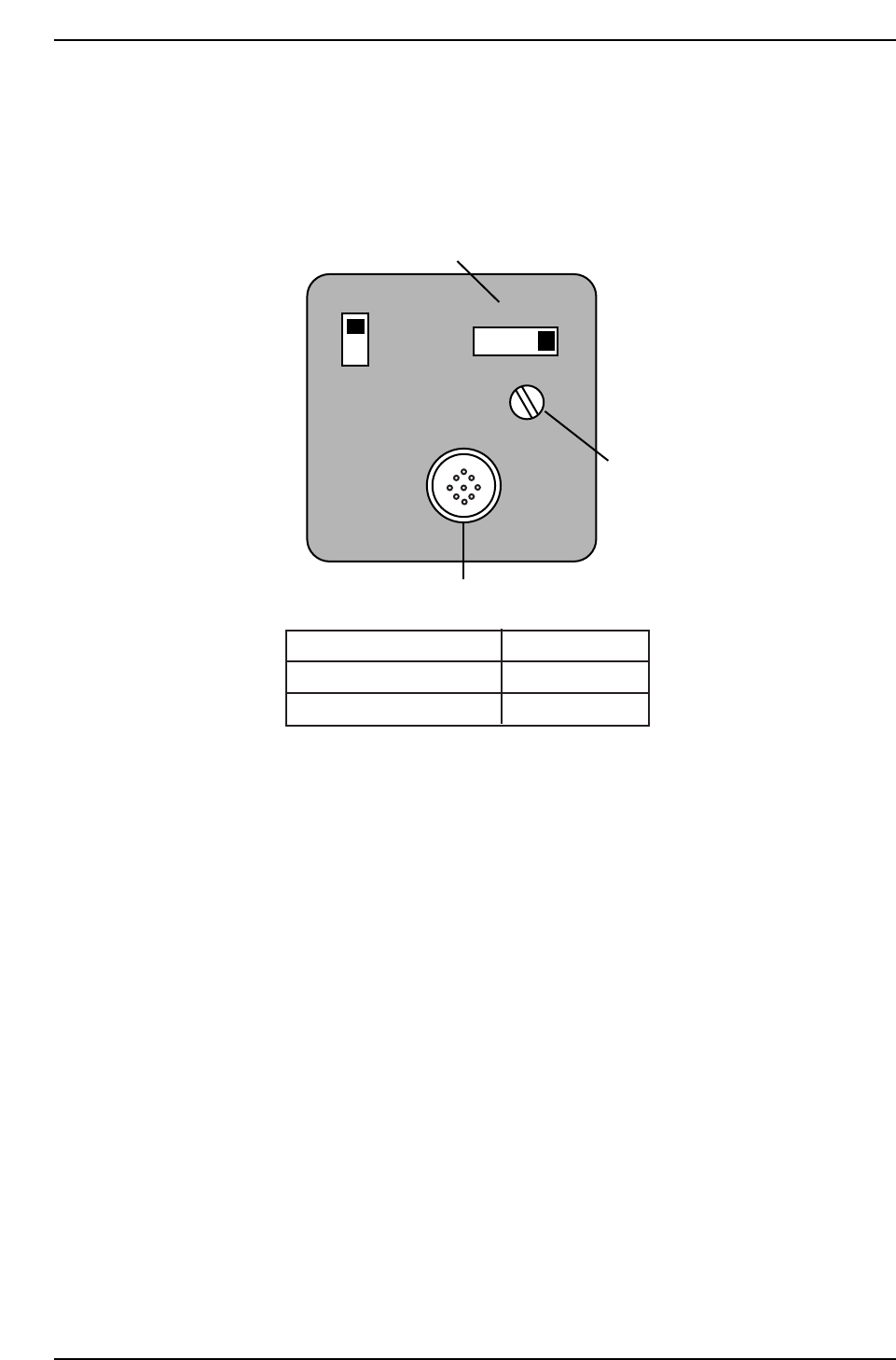
1. Ensure to make the following amplifier and aperture settings prior to
returning the cameras to the machine.
2. Install the lens assembly to the new CCD module and remount the unit
with the two (2) mounting bolts.
3. Reconnect the video cable to the camera unit.
SIGNAL
AFM
1N
1l
Power/Video connector
Gain switch
Manual Gain adj. trimmer
Camera
Apperture
Narrow
Wide
2
2.8
CP7T38005
Chapter 8 8.1 Parts Cameras
Edition 2.0 8-4 CP-7-series Level 3 Tutorial
8.2 Parts Camera Adjustments
8.2.1 Focus Adjustment
Procedure:
1. With the cam at “200°”, open the vacuum spool for the nozzle at Station
5, and place a small leaded (or nozzle jig) part on the nozzle tip.
2. To display a raw image of the part, open the [CCD MONITOR] at the
bottom of the screen, and specify either [WIDE] or [NARROW].
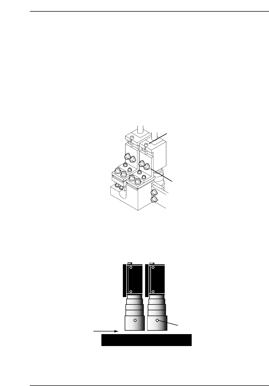
3. Adjust the focus by loosening the two (2) positioning bolts and use the
adjustment bolt to raise and lower the camera (refer to the figure below).
4. Once the camera focus adjustment procedure has been completed for the
wide camera, repeat the procedure for the narrow camera.
5. Loosen the set screw on the lens cover to adjust 0.5 mm above the prism
box surface.
0.5 mm
Set screw
CP7T38007
Adjustment bolts
Positioning bolts
CP7T38006
Chapter 8 8.2 Parts Camera Adjustments
Edition 2.0 8-5 CP-7-series Level 3 Tutorial
8.2.2 Gain Adjustment
Procedure:
1. Insert a clean 0.7 mm nozzle in holder A, nozzle 1. Ensure that the
reflective seal is properly flattened down.
2. Inch the nozzle to 200°, station 5, and view a raw image of the nozzle by
opening the [CCD MONITOR] at the bottom of the screen, and
specifying either [WIDE] or [NARROW].
3. A raw image of the nozzle will now display. Touch the nozzle to display
the pixel value for that area in the bottom right hand corner of the
screen. Adjust the trimmer port on the amplifier for both cameras
The gain value for the reflective seal should ideally be more than 200,
with the nozzle edge more than 160 and the nozzle itself 15.
8.2.3 Camera Centering
Procedure:
1. Perform a nozzle center check procedure in order to ascertain the
straightest 0.7 mm nozzle using both the wide and narrow cameras.
2. Move the nozzle to 200°, station 5, and view the raw image by opening
the [CCD MONITOR] at the bottom of the screen, and specify either
[WIDE] or [NARROW].
3. The CCD monitor will appear on the screen. Press [SCALE] to display
the crosshairs.
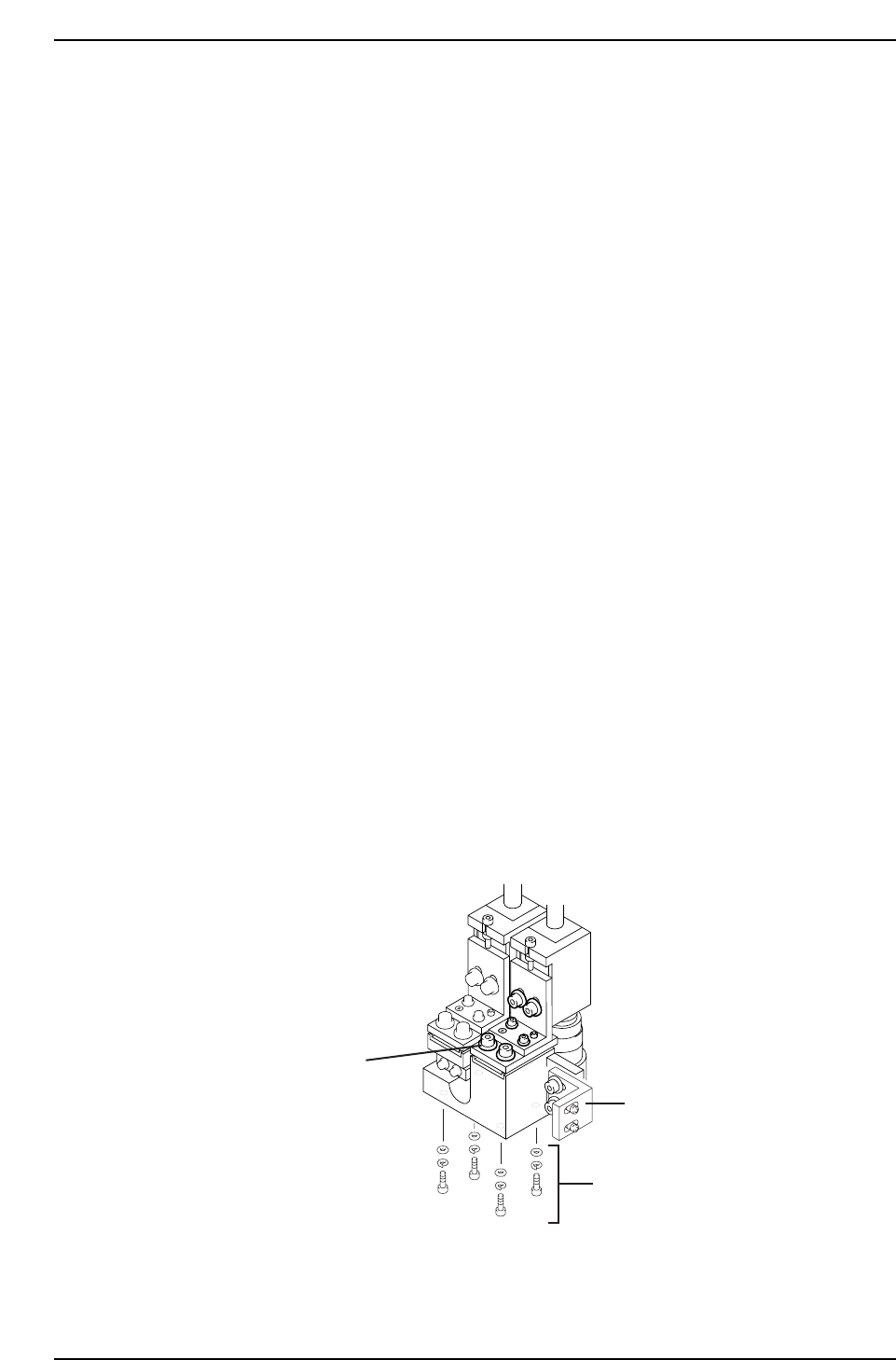
4. First remove the mounting bracket securing the camera assembly to the
right hand inner side of the cam box. It will not be possible to perform
camera adjustments without removing.
Mounting bracket
Wide camera Y-axis
positioning bolts
Wide camera X-axis
positioning bolts
CP7T38008
Chapter 8 8.2 Parts Camera Adjustments
Edition 2.0 8-6 CP-7-series Level 3 Tutorial