CP7 Series Level3 Tutorial Manual.pdf - 第103页
5.1.4 Backlash Adjustment Procedure: 1. Once the alignment adjustment has been completed, remove the jig, then return the adjustment rod and the nozzle holder. 2. Remove the cover from the nozzle changer housing to expos…
5.1.2 Installing the NC-Axis Motor
Procedure:
1. Reattach the gear to the motor and secure the new motor to the machine
with the two (2) mounting bolts.
2. Reconnect the two electrical connectors to the motor.
5.1.3 Nozzle Changer Alignment
Procedure:
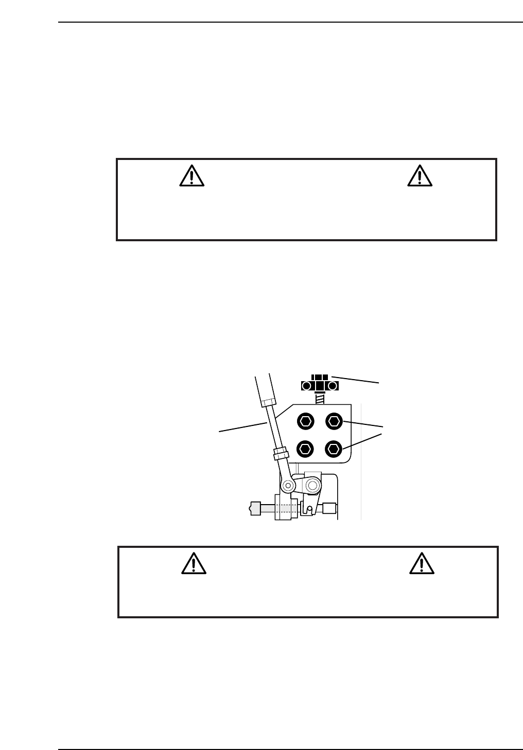
1. Remove the adjustment rod from the lower part of the cam box.
(or alternatively, cut the air supply).
2. Move placing shaft A to 200° at station 14 and install the alignment jig.
3. Loosen the four (4) positioning bolts and lower or raise the bracket using
the adjustment bolts until the nozzle changer clutch slides smoothly into
the jig socket.
Caution
As the alignment jig spans two nozzle shafts, do not move the cam-axis
while the jig is attached.
CN005
Remove Adjustment
Rod
Adjustment
Bolt
Positioning
Bolts
CP7T35003
Notice
Note that as the CP-7 utilizes absolute encoders on all axes, it is no
longer necessary to boot up the machine in Mechacheck mode when
performing motor adjustments.
N001
Chapter 5 5.1 Replacing the NC-Motor
Edition 2.0 5-3 CP-7-series Level 3 Tutorial
5.1.4 Backlash Adjustment
Procedure:
1. Once the alignment adjustment has been completed, remove the jig, then
return the adjustment rod and the nozzle holder.
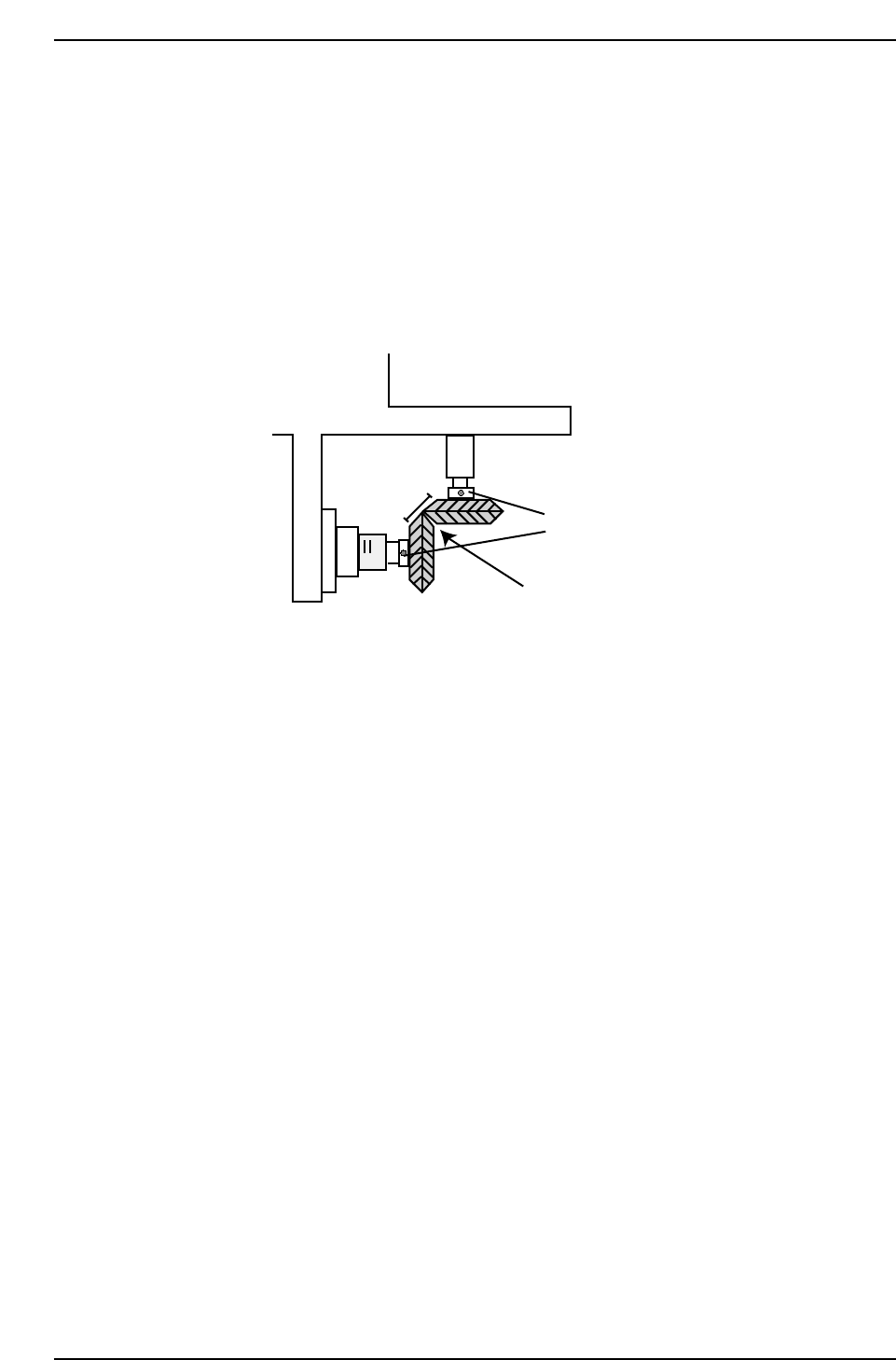
2. Remove the cover from the nozzle changer housing to expose the two
gears inside.
3. Adjust the gears so they mesh cleanly as shown in the diagram below.
4. Loosen the set screws holding the gears in position and adjust so they
mesh cleanly with each other.
5. Place a dial gauge against the lower of the two gauges and measure the
backlash at 0º, 90º, 180º, and 270º. The backlash should be in the range
0.03 to 0.13 mm. If the backlash is not in the range then realign the two
gears as described in step 1.
Ensure corners of gears meet,
creating flat edge
Adjust set screws
CP7T35004
Chapter 5 5.1 Replacing the NC-Motor
Edition 2.0 5-4 CP-7-series Level 3 Tutorial
5.2 NC-Axis Adjustments
5.2.1 NC Origin Position
Procedure:
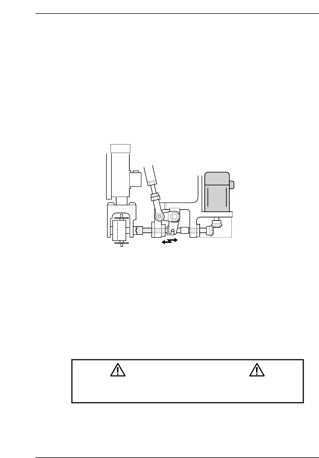
1. Rotate the cam angle to 0°.
2. Activate the nozzle change solenoid valve at the I/O: Y037 NOZZLE
CHANGE SOL ENGAGED.
3. Push the EMERGENCY STOP button to cut the 200V power supply to
the machine and rotate the cam to 141°.
4. Engage the NC clutch rotor with the nozzle holder clutch while holding
the clutch horizontal.
5. Rotate the cam to a position where the clutch starts to engage and where
the backlash decreases for the NC clutch rotation.
6. Rotate the motor gear and note the range of backlash. Take the center
value and set this as the NC origin using the following command:
[MAINTENANCE] → [CALIBRATION] → [ORIGIN POS. OFFSET] →
[SET (NC)].
The resultant value should be no more than ±1800 pulses.
Caution
Ensure that new Calibration data is backed-up to the host computer
once the adjustment procedure is complete.
CN002
14 st
CP7T35005
Chapter 5 5.2 NC-Axis Adjustments
Edition 2.0 5-5 CP-7-series Level 3 Tutorial