CP7 Series Level3 Tutorial Manual.pdf - 第133页
5. To align the crosshairs in the Y-direction, loosen the four (4) bolts on the underside of the camera assembly and adjust the position of the assembly accordingly. Tighten the bolts with the required amount of torque o…
8.2.2 Gain Adjustment
Procedure:
1. Insert a clean 0.7 mm nozzle in holder A, nozzle 1. Ensure that the
reflective seal is properly flattened down.
2. Inch the nozzle to 200°, station 5, and view a raw image of the nozzle by
opening the [CCD MONITOR] at the bottom of the screen, and
specifying either [WIDE] or [NARROW].
3. A raw image of the nozzle will now display. Touch the nozzle to display
the pixel value for that area in the bottom right hand corner of the
screen. Adjust the trimmer port on the amplifier for both cameras
The gain value for the reflective seal should ideally be more than 200,
with the nozzle edge more than 160 and the nozzle itself 15.
8.2.3 Camera Centering
Procedure:
1. Perform a nozzle center check procedure in order to ascertain the
straightest 0.7 mm nozzle using both the wide and narrow cameras.
2. Move the nozzle to 200°, station 5, and view the raw image by opening
the [CCD MONITOR] at the bottom of the screen, and specify either
[WIDE] or [NARROW].
3. The CCD monitor will appear on the screen. Press [SCALE] to display
the crosshairs.
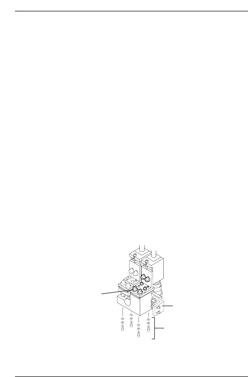
4. First remove the mounting bracket securing the camera assembly to the
right hand inner side of the cam box. It will not be possible to perform
camera adjustments without removing.
Mounting bracket
Wide camera Y-axis
positioning bolts
Wide camera X-axis
positioning bolts
CP7T38008
Chapter 8 8.2 Parts Camera Adjustments
Edition 2.0 8-6 CP-7-series Level 3 Tutorial
5. To align the crosshairs in the Y-direction, loosen the four (4) bolts on the
underside of the camera assembly and adjust the position of the
assembly accordingly. Tighten the bolts with the required amount of
torque once the adjustment is complete (torque = 13 Nm).
Note: As the narrow camera bracket rests upon the wide camera bracket, it is necessary to
adjust the wide camera bracket first when adjusting both cameras. Performing narrow
camera adjustments first will necessitate the adjustment being performed twice.
6. To align the crosshairs in the X-direction, loosen the X-axis positioning
bolts on the front of the camera bracket and adjust the position of the
camera accordingly. Tighten the bolts with the required amount of
torque once the adjustment is complete (torque = 8 Nm).
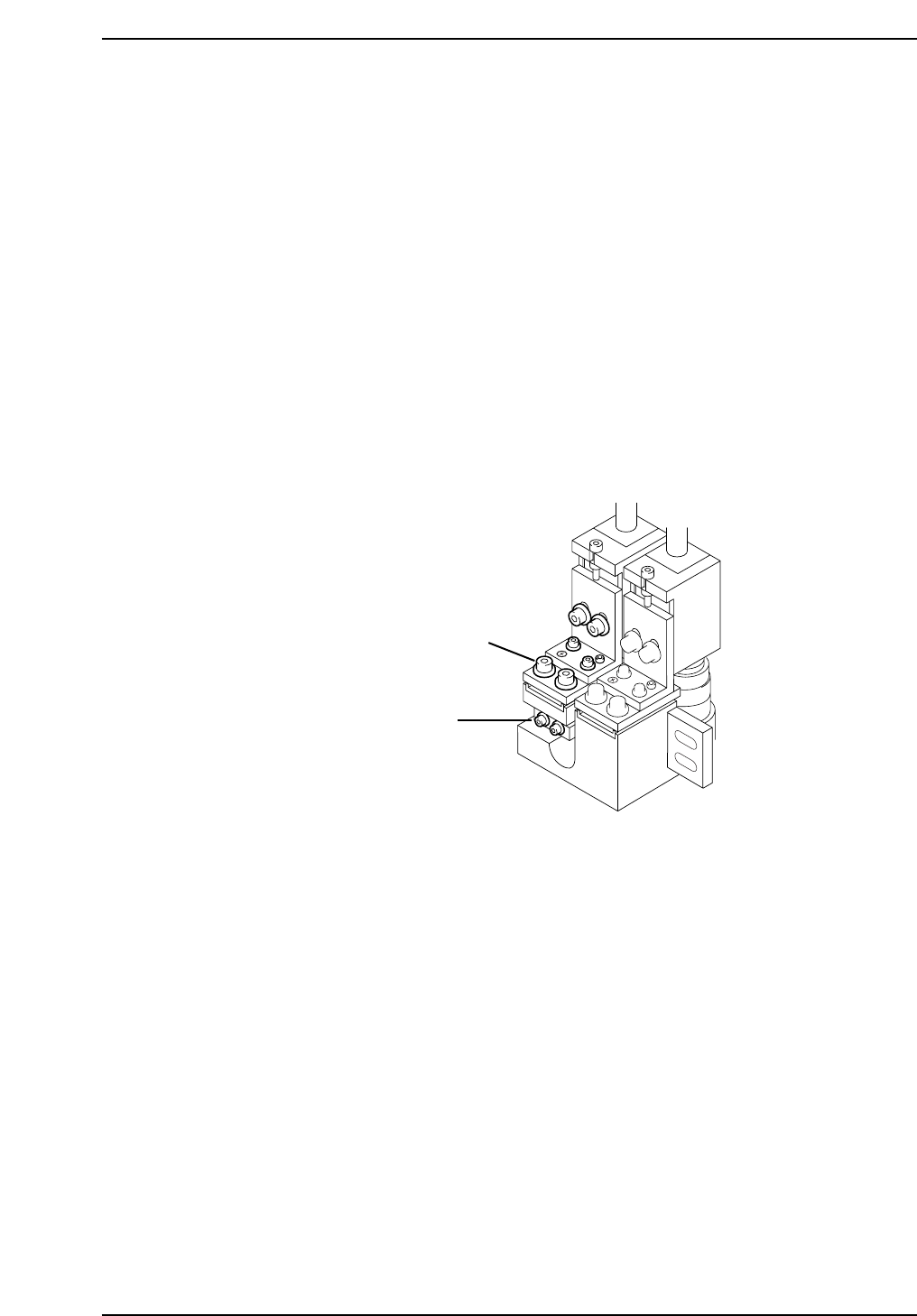
7. To adjust the narrow camera in the Y-direction, loosen the Y-axis
positioning bolts as shown below and adjust the camera position
accordingly. Tighten the bolts with the required amount of torque once
the adjustment is complete (torque = 13 Nm).
8. To adjust the narrow camera in the X-direction, loosen the X-axis
positioning bolts as shown below and adjust the camera position
accordingly. Tighten the bolts with the required amount of torque once
the adjustment is complete (torque = 8 Nm).
8.2.4 Camera Skew and Resolution
The camera skew adjustment is performed in order to align the camera with the X and Y-
axes of the machine. This is vital when determining accurate angular compensation at
station 8 (FQ).
The camera resolution indicates the size in the X and Y-direction of a pixel. If the camera
resolution lies outside the specified range, the dimensions of the measured part will not
match the data contained in the part data, and a vision processing error will occur.
Narrow camera X-axis
positioning bolts
Narrow camera Y-axis
positioning bolts
CP7T38009
Chapter 8 8.2 Parts Camera Adjustments
Edition 2.0 8-7 CP-7-series Level 3 Tutorial
8.2.4.1 Adjusting the Wide Camera
Procedure:
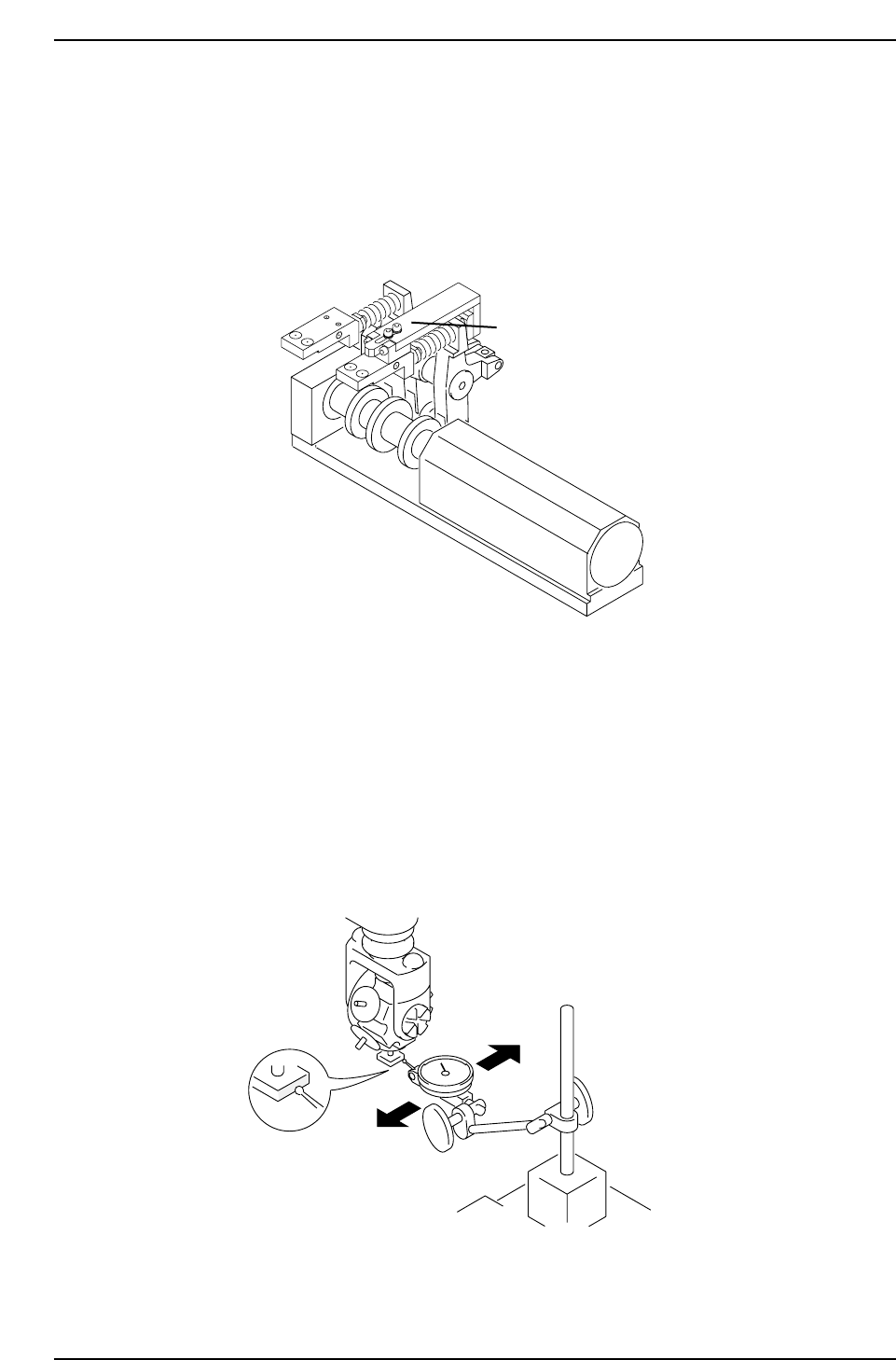
1. Install the cam lever stopper jig as shown in the diagram below before
the clutch descends with the cam at 0°. This will prevent the clutch
descending during measurement.
2. Insert a By-pass key into both front door interlocks.
3. Attach the wide camera nozzle jig on Head A No.1, at station 9.
4. Remove the back-up pin plates and attach the XY-table magnet stand to
the XY-table.
5. Rotate the shaft with the jig attached to 200° station 9 with the pick-up
solenoid off. Set the dial gauge to the stand and attach the needle to the
horizontal flat edge of the jig.
CP7T38011
Station 8
Attach jig here
CP7T38010
Cam Shaft A
Chapter 8 8.2 Parts Camera Adjustments
Edition 2.0 8-8 CP-7-series Level 3 Tutorial