CP7 Series Level3 Tutorial Manual.pdf - 第26页
1.1 Replacing the X-Motor The X-motor (refer to figure below) is responsible for moving the production table to the left and right inside the machine (as viewed from the front of the machine). This allows the PCB to be a…

Chapter 1
X, Y, and Z-Axes
Objective:
Given a CP-7-series machine, technical
documentation and required tools,
remove, replace and calibrate the X, Y,
and Z-motors to FUJI specifications.
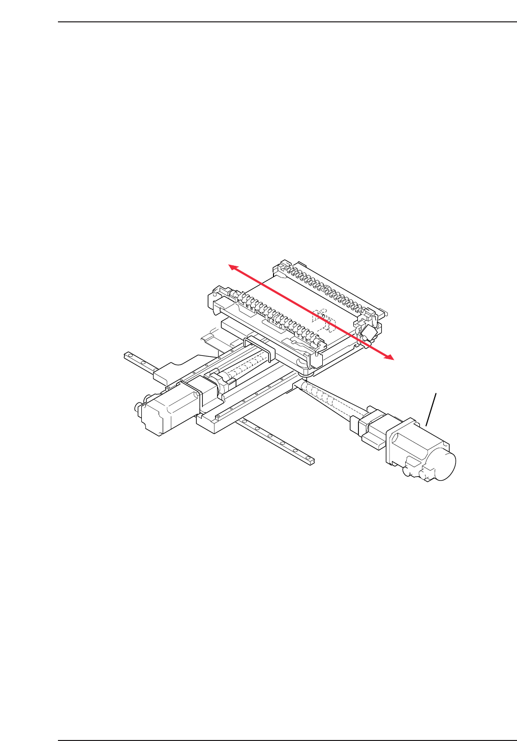
1.1 Replacing the X-Motor
The X-motor (refer to figure below) is responsible for moving the production table
to the left and right inside the machine (as viewed from the front of the machine).
This allows the PCB to be accurately positioned underneath the placing heads for
part placement.
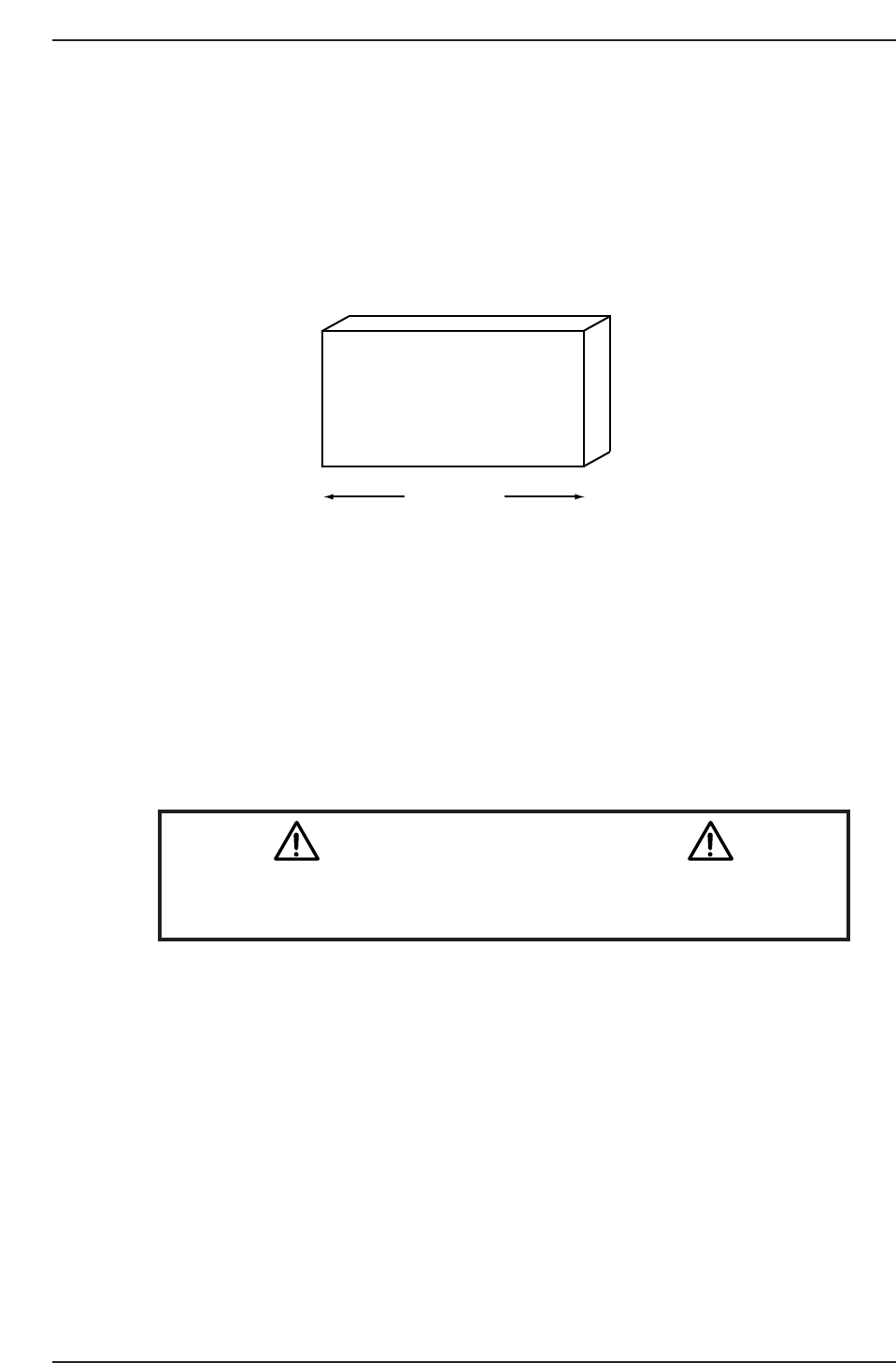
A poorly adjusted or problematic X-axis will result in placement offset in the left
and right direction. Recalibration of the X-axis is needed to eradicate this problem.
• Damage or slippage of the coupling that connects the X-motor and the X-axis ball
screw.
• After replacing the X-motor
• After replacing the OT sensors, etc.
X-axis motor
CP7T31001
Chapter 1 1.1 Replacing the X-Motor
Edition 2.0 1-1 CP-7-series Level 3 Tutorial
Required Tools: 1 Set of Allen Wrenches
1 Phillips Screwdriver
1 Torque Wrench
Required Jig: 155 mm spacer
Resolution: 0.002 mm/pulse World (Zero)
Affected Proper: Max Limit X → MC0MAXX
Min Limit X → MC0MINX
Caution
Ensure that a back-up of Proper data is taken prior to replacing the
motor.
CN001
155 mm
Z9426DCPJ6090
CP7T31002
CP-732E
Chapter 1 1.1 Replacing the X-Motor
Edition 2.0 1-2 CP-7-series Level 3 Tutorial