CP7 Series Level3 Tutorial Manual.pdf - 第75页
3.1.2 Installing the D-Axis Motor Procedure: 1. Secure the new motor to the machine with the two (2) allen extension bolts and two (2) allen bolts. 2. Reconnect the two (2) electrical connectors to the motor. Note: Do no…
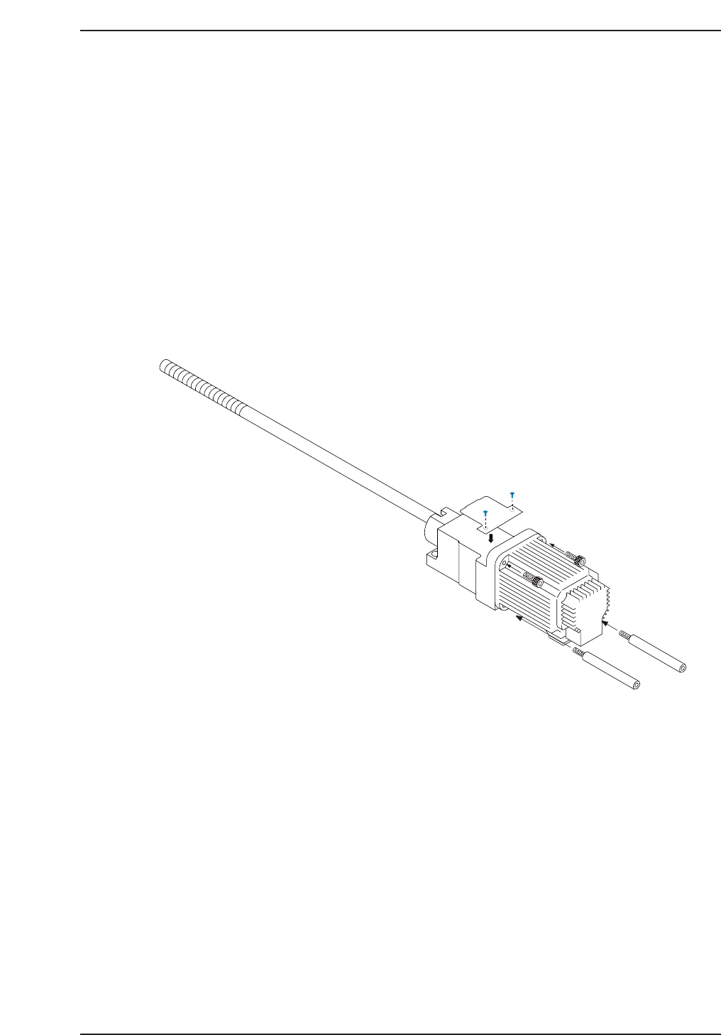
3.1.1 Removing the D-Axis Motor
Procedure:
1. Turn OFF the machine power.
2. Inch the D2-table in the direction of the D1-table in order to gain access
to the motor (D1).
3. Disconnect both electrical connections to the motor.
4. Remove the two (2) Phillips head screws securing the cover over the
coupling, and take off the cover.
5. Loosen the coupling on the motor side to separate the motor from the
ball screw (refer to the figure below).
6. Disconnect the two (2) electrical connections from the motor.
7. Remove the two (2) allen extension bolts (bottom) and the two (2) allen
bolts (top) securing the motor to the machine and then remove the
motor.
CP7T33003
Chapter 3 3.1 Replacing the D-Axis Motor
Edition 2.0 3-3 CP-7-series Level 3 Tutorial
3.1.2 Installing the D-Axis Motor
Procedure:
1. Secure the new motor to the machine with the two (2) allen extension
bolts and two (2) allen bolts.
2. Reconnect the two (2) electrical connectors to the motor.
Note: Do not tighten the coupling at this stage.
Notice
Note that as the CP-7 utilizes absolute encoders on all axes, it is no
longer necessary to boot up the machine in Mechacheck mode when
performing motor adjustments.
N001
Chapter 3 3.1 Replacing the D-Axis Motor
Edition 2.0 3-4 CP-7-series Level 3 Tutorial
3.2 D-Axis Adjustments
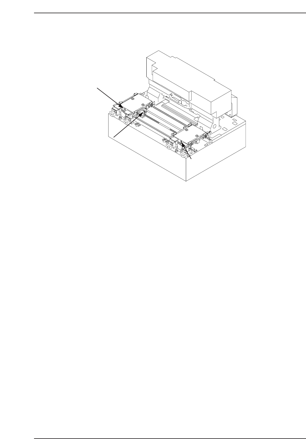
3.2.1 Minus Overtravel Sensor Adjustment
Procedure:
1. Remove both feeder pallets prior to adjusting.
2. Manually move table 2 (table 1) towards the center of the axis to gain
access to the D1 (D2) motor. Remove the two (2) Phillips head screws
securing the cover over the coupling, and take off the cover. Loosen the
for allen bolts securing the coupling.
3. Temporarily remove both minus overtravel dogs, then inch the D1-
motor to 5000 (-5000 for D2) pulses. Push the D1 table against the plus
mechanical stopper (D2 against the minus mechanical stopper), and
tighten the coupling. D-axis coupling torque = M5: 8.3 N.m, M4: 4 Nm.
(CP-742E(ME): all 8.3 N.m).
4. Push the EMERGENCY STOP button, and pull the D1 (D2) table back
against the stopper again. Record the motor pulse count at this point.
5. Replace the -OT dog and adjust to activate the sensor at the point 3500
pulses back from the stopper. Record the counter value.
6. Move back an additional 500 pulses from the position at which the
minus OT sensor activates and set this position in calibration data as the
D1 Max Limit Pos (D2: Min Limit Pos). using the following commands:
[MAINTENANCE] → [CALIBRATION] → [TRAVEL LIMITS] → [MAX
LIMIT POS.] (D2: [MIN LIMIT POS]).
7. Confirm the sensor reaction using the I/O commands:
SX042 D1 AXIS -OT
SX04A D2 AXIS -OT
D1 - OT sensor
(SX042 D1-AXIS -OT)
D2 -OT sensor
(SX04A D2-AXIS -OT)
Interference prevention
sensor
(SX041 D1-AXIS +OT/
SX049 D2-AXIS +OT)
Table 1
Table 2
CP7T33004
Chapter 3 3.2 D-Axis Adjustments
Edition 2.0 3-5 CP-7-series Level 3 Tutorial