CP7 Series Level3 Tutorial Manual.pdf - 第35页
Required Tools: 1 Set of Allen Wrenches 1 Phillips Screwdriver 1 Torque Wrench Required Jig: 155 mm spacer Resolution: 0.002 mm/pulse World (Zero) Affected Proper: Max Limit Y → MC0MAXY Min Limit Y → MC0MINY Caution Ensu…
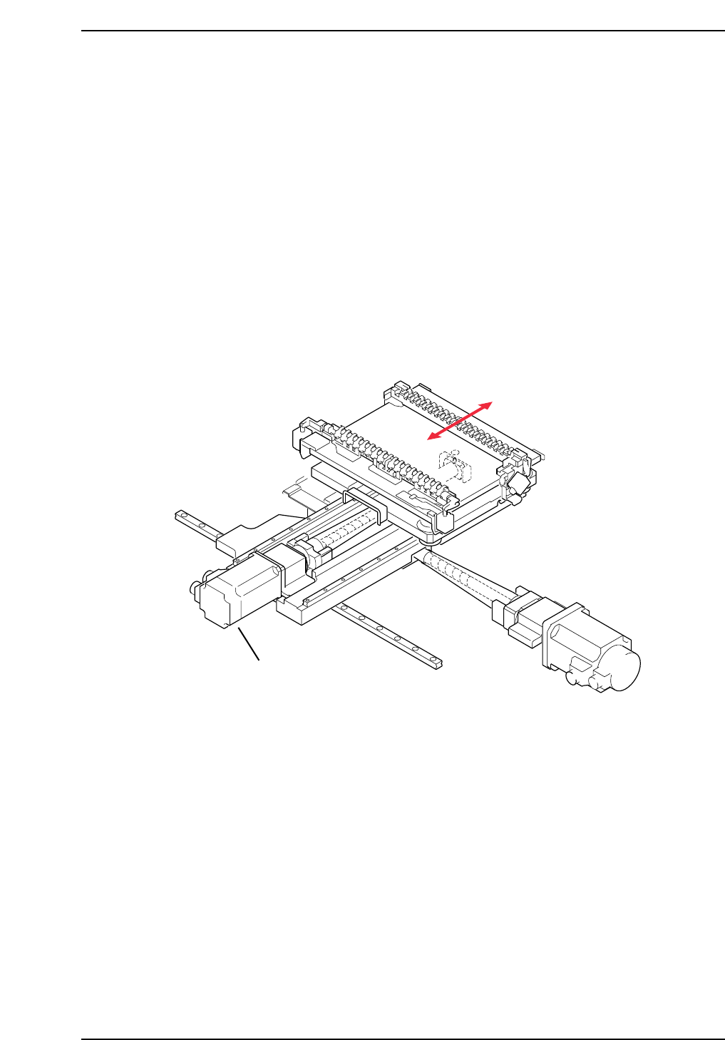
1.3 Replacing the Y-Motor
The Y-motor (refer to figure below) is responsible for moving the production table
to the front and rear inside the machine (as viewed from the front of the machine).
This allows the PCB to be accurately positioned underneath the placing heads for
part placement.
A poorly adjusted or problematic Y-axis will result in placement offset in the up
and down direction. Recalibration of the Y-axis is needed to eradicate this
problem.
• Damage or slippage of the coupling that connects the Y-motor and the Y-axis ball
screw.
• After replacing the Y-motor
• After replacing the OT sensors, etc.
CP7T31008
Y-axis motor
Chapter 1 1.3 Replacing the Y-Motor
Edition 2.0 1-9 CP-7-series Level 3 Tutorial
Required Tools: 1 Set of Allen Wrenches
1 Phillips Screwdriver
1 Torque Wrench
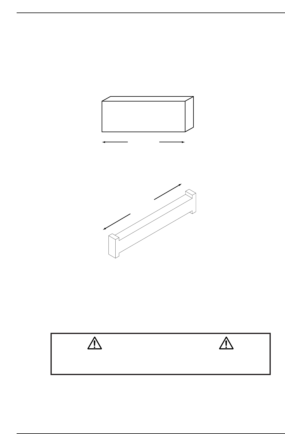
Required Jig: 155 mm spacer
Resolution: 0.002 mm/pulse World (Zero)
Affected Proper: Max Limit Y → MC0MAXY
Min Limit Y → MC0MINY
Caution
Ensure that a back-up of Proper data is taken prior to replacing the
motor.
CN001
155 mm
CP7T31009
Z9426DCPJ5680
225 mm
DGPJ0161
CP732E
CP742E(ME)
Chapter 1 1.3 Replacing the Y-Motor
Edition 2.0 1-10 CP-7-series Level 3 Tutorial
Chapter 1 1.3 Replacing the Y-Motor
Edition 2.0 1-11 CP-7-series Level 3 Tutorial
1.3.1 Removing the Y-Axis Motor
Procedure:
1. Turn OFF the machine power.
2. Remove the front cover from the machine in order to gain access to the
motor.
3. Retract both the IN and OUT carriers, and widen the machine’s conveyor
rails to allow better access to the machine.
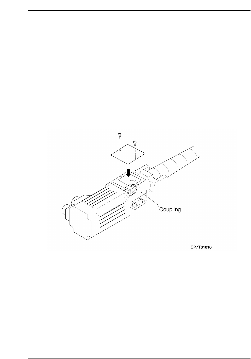
4. Push the motor away from the stopper and remove the two (2) Phillips
head screws securing the cover over the coupling.
5. Loosen the coupling on the motor side to separate the motor from the
ball screw (refer to the figure below).
6. Disconnect the two (2) electrical connections from the motor.
7. Remove the four (4) allen extension bolts securing the motor to the
machine and then remove the motor.