CP7 Series Level3 Tutorial Manual.pdf - 第46页
Chapter 1 1.5 Replacing the Z-Motor Edition 2.0 1-21 CP-7-series Level 3 T utorial 5. Loosen the lock nut at corner B and use an allen wrench to adjust the height of the table until the dial reads 0. Move the dial back t…
Chapter 1 1.5 Replacing the Z-Motor
Edition 2.0 1-20 CP-7-series Level 3 Tutorial
1.5.2 Installing the Z-Axis Motor
Procedure:
1. Secure a new motor to the machine.
2. Reconnect the two (2) electrical connectors to the motor.
3. Replace the motor and fasten in place with the four (4) mounting bolts.
4. Replace the table top and secure using the lock nut jig.
1.5.3 Adjusting the Table Top Parallelism
There may be occasions where it is necessary to adjust the parallelism of the table top.
An excessively uneven table top will result in damaged nozzles in some areas and
tombstoning of parts in others.
Procedure:
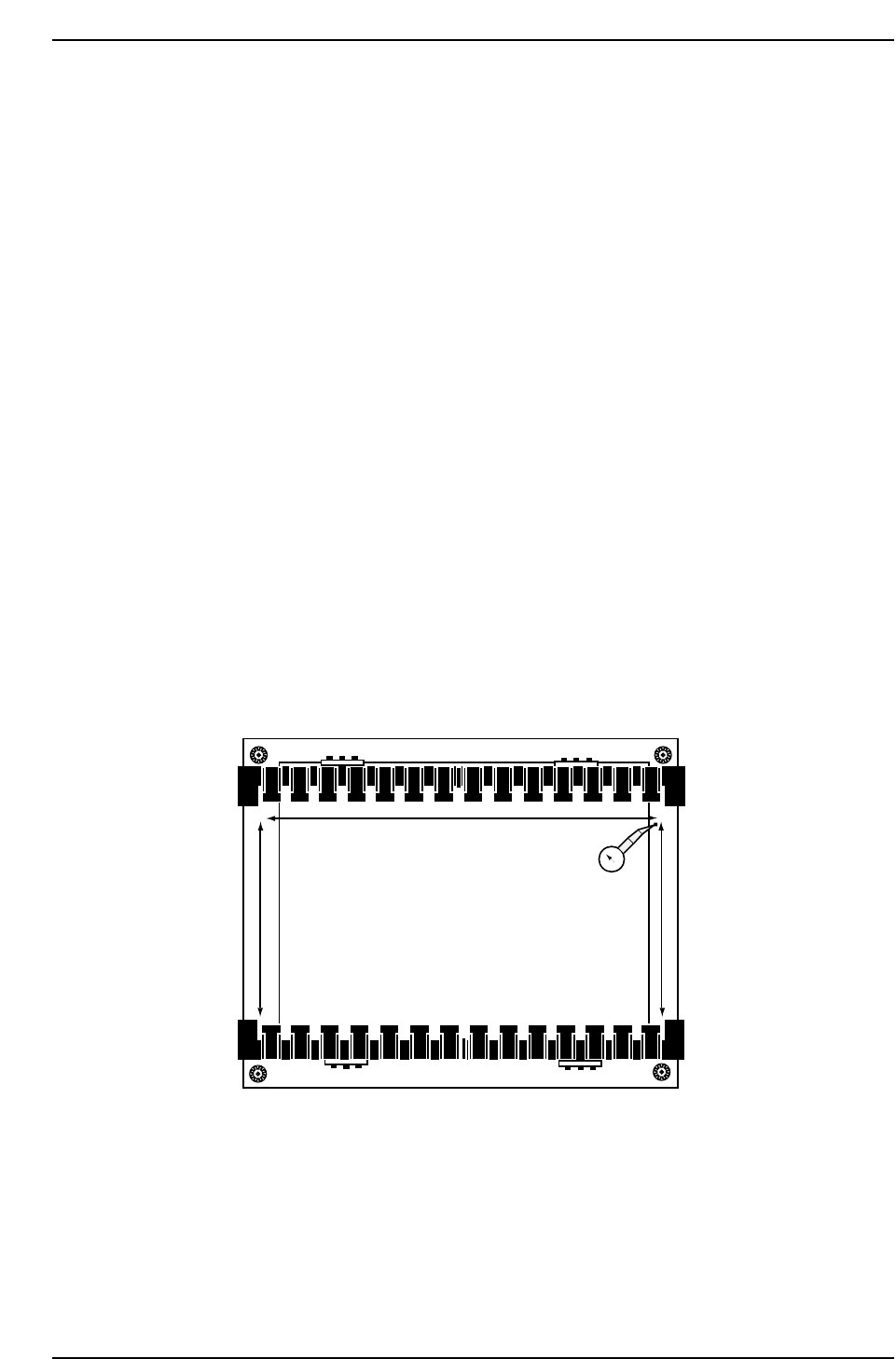
1. Push the adjustable rail towards the back of the table, while ensuring to
leave the lock nuts exposed.
2. Inch the table in the X and Y-directions towards their respective minus
side mechanical stoppers, while taking care not to enter overtravel.
3. Attach a dial gauge to the Fiducial camera bracket and attach the needle
to point A (refer to diagram below).
4. Using A as the reference point, set the dial gauge to zero and inch in the
Y-direction to take the needle to point B.
CP7T31018
0
A
B
C
D
XY-Table
Chapter 1 1.5 Replacing the Z-Motor
Edition 2.0 1-21 CP-7-series Level 3 Tutorial
5. Loosen the lock nut at corner B and use an allen wrench to adjust the
height of the table until the dial reads 0. Move the dial back to point A
and re-check.
Note: The reference point should always be zero.
6. Now inch in the X-direction to move the dial to point C. Adjust to zero
using the lock nut jig and allen wrench. Repeat for C to D.
7. Finally re-check and ensure that the tolerance for whole table is no more
than 0.2 mm.
1.5.4 Main Clamper Parallelism
Once the table top leveling has been performed, it is necessary to perform the main
clamper parallelism adjustment.
Procedure:
1. Use an allen wrench to loosen all claws on both the fixed and adjustable
rails. Loosen the top claws only.
Note: It is impossible to inch the XY-table when the clamper is open
2. Disconnect the air supply and move the adjustable rail back
approximately 50 mm.
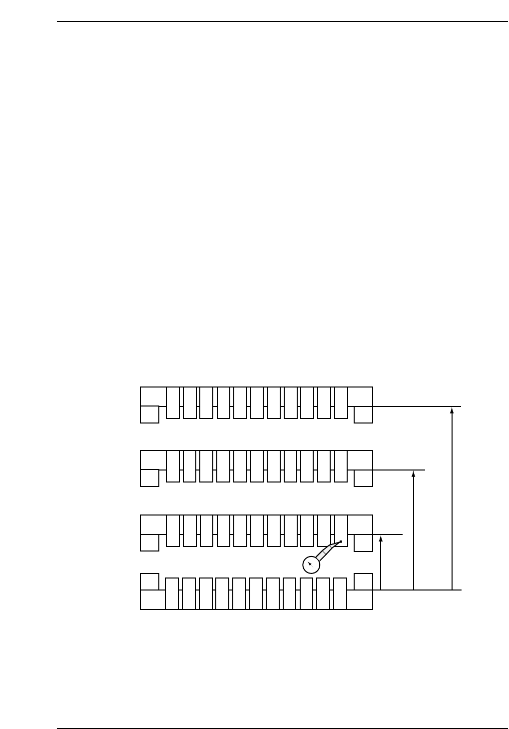
3. Set the dial gauge to zero at point zero as shown in the diagram below.
4. Inch the table in the X-direction and measure the deflection on the dial
gauge at points 2 and 3. Then measure points 10, 11 and 12 with respect
to point 1.
Note: Adjust at ZØ to ensure that there is no interference between the opened claws and the
cutter plate.
101112
123
456
789
50 mm
180 mm
250 mm
0
CP7T31019
Chapter 1 1.5 Replacing the Z-Motor
Edition 2.0 1-22 CP-7-series Level 3 Tutorial
5. Move the adjustable rail back 180 mm from the fixed rail and measure at
points 4, 5 and 6. Finally, repeat for points 7, 8 and 9 at 250 mm from the
fixed rail.
6. Ensure that points 1, 3, 7, 9, 10 and 12 are within range.
7. To adjust, move the adjustable rail back to 180 mm and use the lock nut
jig and allen wrench to raise or lower the two rear corners until both
points 4 and 6 fall within or up to 0 ± 0.1 mm from point 1.
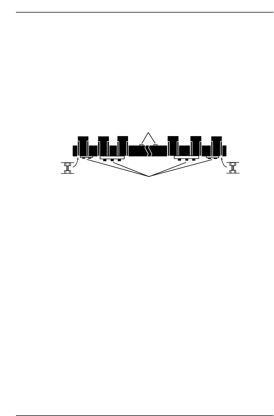
8. Raise and lower the fixed rail using the two (2) adjustment bolts as
shown in the diagram below.
9. Total tolerance for the whole board is 0.15 mm (if possible 0.1 mm).
1.5.5 Fixed Rail Linearity
Once the table top and clamper parallelism adjustments have been carried out, confirm
and if necessary, adjust the linearity of the fixed rail. Failure to straighten the rail within
permissible limits will result in clamping problems or skewed PCBs.
Procedure:
1. With all the clamper claws on the fixed rail open, position the dial on the
vertical edge of the clamper claw at position A (refer to diagram on the
opposite page).
2. Set the dial gauge to zero and inch in the X-direction at 1% inching speed
to position B. Note the dial gauge reading.
3. Inch from position B to position C and note the dial gauge reading. The
dial gauge should show no more than a 0.1 mm deflection at either point.
4. If the dial gauge deflection exceeds the permissible tolerance, loosen all
bolts as shown in the diagram opposite.
5. Again, zero the dial gauge at position A, and inch to position B. If the
deflection exceeds 0.1 mm, tap lightly on the clamper at point C until the
dial gauge registers zero. Zero again at point A, and inch to B. If at zero,
partially tighten the allen bolts at point E and F.
Loosen all ten bolts
Fixed rail height
adjustment bolt
Fixed rail height
adjustment bolt
CP7T31020
Loosen two bolts
on rear side