CP7 Series Level3 Tutorial Manual.pdf - 第83页
Notes: Chapter 3 3.2 D-Axis Adjustments Edition 2.0 3-12 CP-7-series Level 3 T utorial
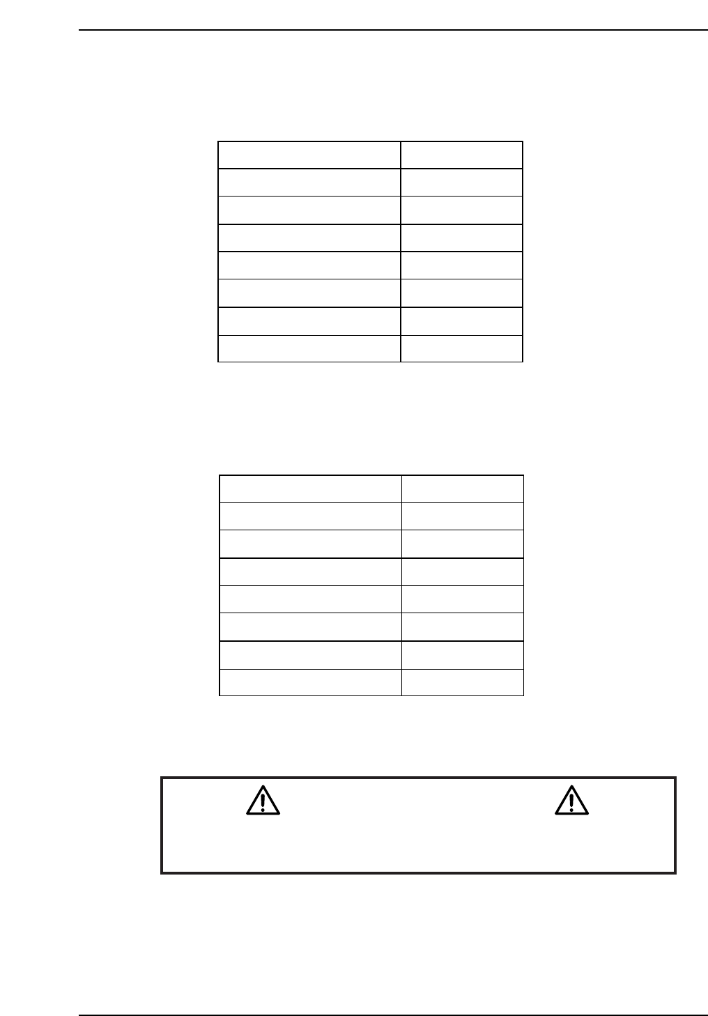
CP-742ME Calibration Data Servo Count Chart (D1-axis)
CP-742ME Calibration Data Servo Count Chart (D2-axis)
Caution
Ensure that new Calibration data is backed-up to the host computer
once the adjustment procedure is complete.
CN002
CP7T33014
Minus mechanical stopper
+OT sensor ON
Max limit pos.D2
D2 Origin
Pickup pos. T2
-OT sensor ON
Plus mechanical stopper
-5000 ± 50
-1500 ± 50
-1000 ± 50
0 ± 1000
351300
Min limit pos. D2 673500 ± 1000
677500 ± 1000
674000 ± 1000
CP7T33013
Plus mechanical stopper
-OT sensor ON
Max limit pos.D1
D1 Origin
Pickup pos. T1
+OT sensor ON
Minus mechanical stopper
5000 ± 50
1500 ± 50
1000 ± 50
0 ± 1000
-670700
Min limit pos. D1 -673500 ± 1000
-677500 ± 1000
-674000 ± 1000
Chapter 3 3.2 D-Axis Adjustments
Edition 2.0 3-11 CP-7-series Level 3 Tutorial

Notes:
Chapter 3 3.2 D-Axis Adjustments
Edition 2.0 3-12 CP-7-series Level 3 Tutorial
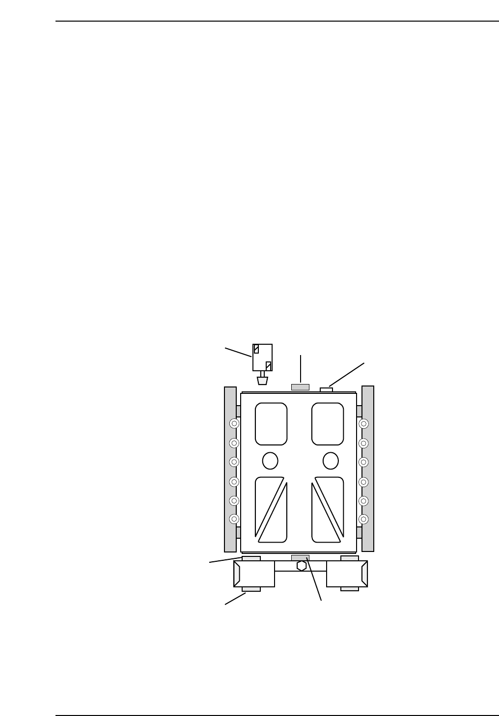
3.3 D-Axis Pallet Adjustments
3.3.1 Pallet Upper/Lower End Sensor Adjustments
Procedure:
1. Inch the axis to the counter zero position (10 mm from the stopper).
2. Move the pallet to the upward end by manually operating the pallet
upward solenoid valve.
3. Insert the Pallet Change Unit (PCU) and lock in position. Move the
pallet to the PCU. Remove the PCU.
4. Place a 0.5 mm feeler gauge on the four pallet clamp surfaces.
5. Slide the pallet back into position and ensure that it contacts the stopper
(2).
6. Lower the pallet with a 0.5 mm feeler gauge between the jig and the four
clamp surfaces. Adjust the sensor position so that the pallet lower end
sensor (3) turns OFF at this position and activates when the 0.5 mm
feeler gauges are removed
7. Next adjust the upward end sensor (4) so that the sensor turns OFF when
lowered 0.5 mm from the upward end.
7
(3, 4)
2
5
6
3
CP7T33015
Chapter 3 3.3 D-Axis Pallet Adjustments
Edition 2.0 3-13 CP-7-series Level 3 Tutorial