CP7 Series Level3 Tutorial Manual.pdf - 第92页
Required Tools: 1 Set of Allen Wrenches 1 Tension Meter 1 Metric Dial Gauge and Stand Required Jig: Q-axis Alignment Jig Resolution: 0.002 mm/pulse World (Zero) Affected Calibration data: PQ Origin Pos. → MC0ZOVPQ PQ Ori…
4.1 Replacing the Q-Motors
PQ Motor
The FQ-motor (refer to figure below) is responsible for rotating the placing shaft at
station 2 in increments of +90° or -90°, depending on the part placing angle
specified in the production program.
Any failure of the PQ-axis will result in inaccurate results when vision processed
at station 5, and subsequently offset placing angle.
FQ-Motor
The FQ-motor (refer to figure below) is responsible for rotating the placing shaft at
station 8 in at the compliment of the rotational angle performed at station 2,
depending on the placing angle specified in the production program.
Any failure of the FQ-axis will result in inaccurate component placing angle at
station 9.
RQ-Motor
The RQ-motor (refer to figure below) is responsible for rotating the placing shaft at
station 10 minus the sum of both rotations at PQ and FQ.
Any failure of the RQ-axis will result in a station 13 Nozzle prechange check.
Some examples of possible reasons for recalibration are:
- Damage or slippage of the timing belt which connects the Q-axes motor
gear and the axis itself.
- After replacement of the Q-motor.
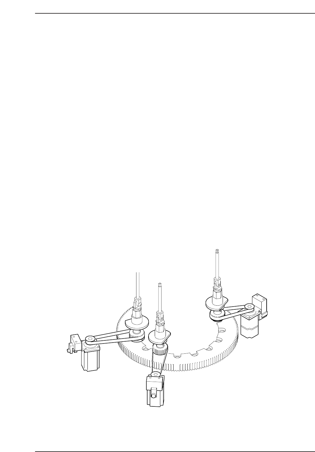
PQ (ST.2)
FQ (ST.8)
RQ (ST.10)
CP7T34001
Chapter 4 4.1 Replacing the Q-Motors
Edition 2.0 4-1 CP-7-series Level 3 Tutorial
Required Tools: 1 Set of Allen Wrenches
1 Tension Meter
1 Metric Dial Gauge and Stand
Required Jig: Q-axis Alignment Jig
Resolution: 0.002 mm/pulse World (Zero)
Affected Calibration data: PQ Origin Pos.→ MC0ZOVPQ
PQ Origin Pos.→ MC0ZOVFQ
PQ Origin Pos.→ MC0ZOVRQ
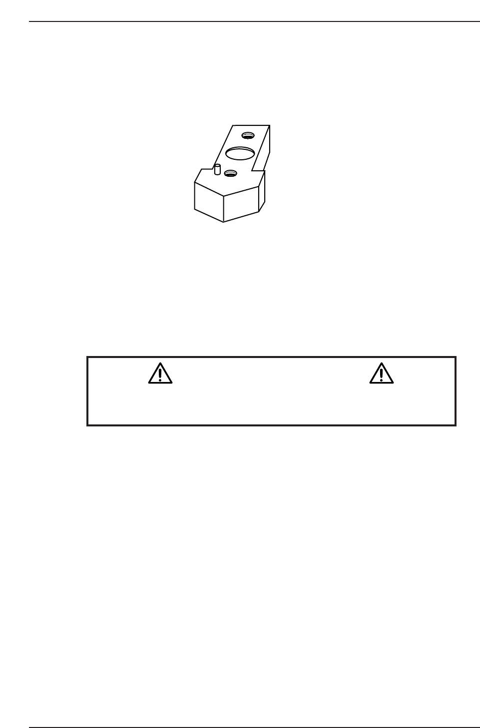
Caution
Ensure that a back-up of Proper data is taken prior to replacing the
motor.
CN001
ADCPJ8230
CP7T34002
Chapter 4 4.1 Replacing the Q-Motors
Edition 2.0 4-2 CP-7-series Level 3 Tutorial
4.1.1 Removing the Q-Axis Motor
Procedure:
1. Turn OFF the machine power.
2. Disconnect both electrical connections to the motor.
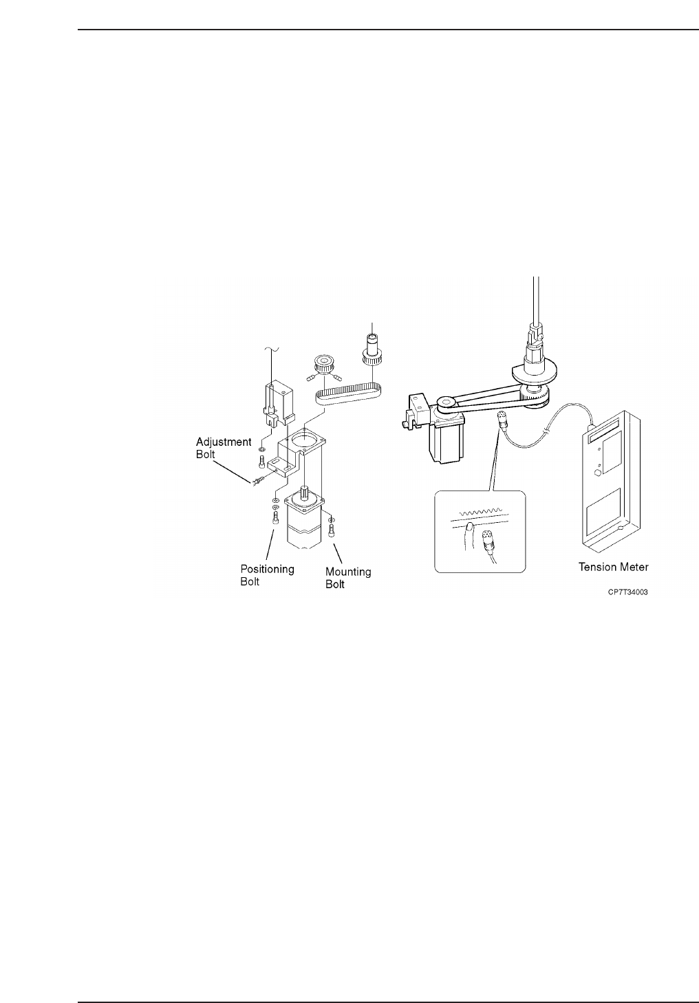
3. Loosen the two (2) bolts on the underside of the timing belt adjustment
bracket, then adjust the jack bolt to lower the timing belt tension.
4. Remove the timing belt.
5. Separate the gear from the motor by loosening the set screw and remove.
6. Remove the four (4) positioning bolts fixing the motor to the mounting
bracket and then remove the motor.
4.1.2 Installing the Q-Axis Motor
Procedure:
1. Replace the motor and secure in place using the four (4) positioning
bolts.
2. Replace the motor gear and secure by tightening the set screw.
3. Replace the timing belt and adjust the tension as shown above according
to the table on the following page.
Chapter 4 4.1 Replacing the Q-Motors
Edition 2.0 4-3 CP-7-series Level 3 Tutorial