CP7 Series Level3 Tutorial Manual.pdf - 第56页
Chapter 2 X, Y , and Z-Axes Calibration Data Measurements Objective: Given a CP-7-series machine, technical documentation and required tools, perform X, Y , and Z-axes calibration data adjustments to FUJI specifications.

Chapter 1 1.7 Training Evaluation
Edition 2.0 1-30 CP-7-series Level 3 Tutorial
Notes:

Chapter 2
X, Y, and Z-Axes
Calibration Data
Measurements
Objective:
Given a CP-7-series machine, technical
documentation and required tools,
perform X, Y, and Z-axes calibration
data adjustments to FUJI specifications.
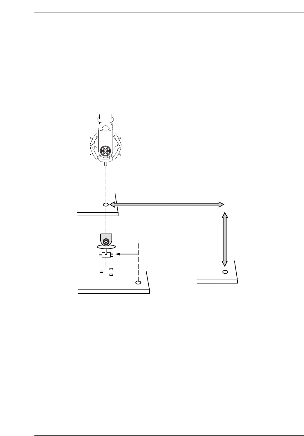
2.1 Placing Position (XØ, YØ)
Placing position X and Y positions correspond to the X and Y servo counter values
that are required to move the XY-table from the zero pulse position in the X and Y-
axes to the position where the program origin (-5,5) in the case of Fuji machines) is
aligned with the center of the nozzle on Head A at station 9. One pulse
corresponds to 0.002 mm.
If an incorrect value is input for XØ, YØ, component placement will be off by an
amount equal to the error (refer to the figure below).
Required Tools: None
Required Jigs: Pin holder jig
Centering gauge
Centering jig
Dial holder
Dial gauge
Placing Position Y
Program
Coordinates
CP7T32001
11 St
Placing Position X
Chapter 2 2.1 Placing Position (XØ, YØ)
Edition 2.0 2-1 CP-7-series Level 3 Tutorial