CP7 Series Level3 Tutorial Manual.pdf - 第50页
Chapter 1 1.6 Z-Axis Adjustments Edition 2.0 1-25 CP-7-series Level 3 T utorial 1.6 Z-Axis Adjustments Procedure: 1. Before performing Z-axis adjustments, it is necessary to adjust the Z-axis timing belt tension. Ensure …
Chapter 1 1.5 Replacing the Z-Motor
Edition 2.0 1-24 CP-7-series Level 3 Tutorial
5. Tighten all bolts and recheck.
6. Finally, tighten all the clamper claws, ensuring a gap of at least 0.1 mm.
1.5.7 Reference Pin Adjustment
Procedure:
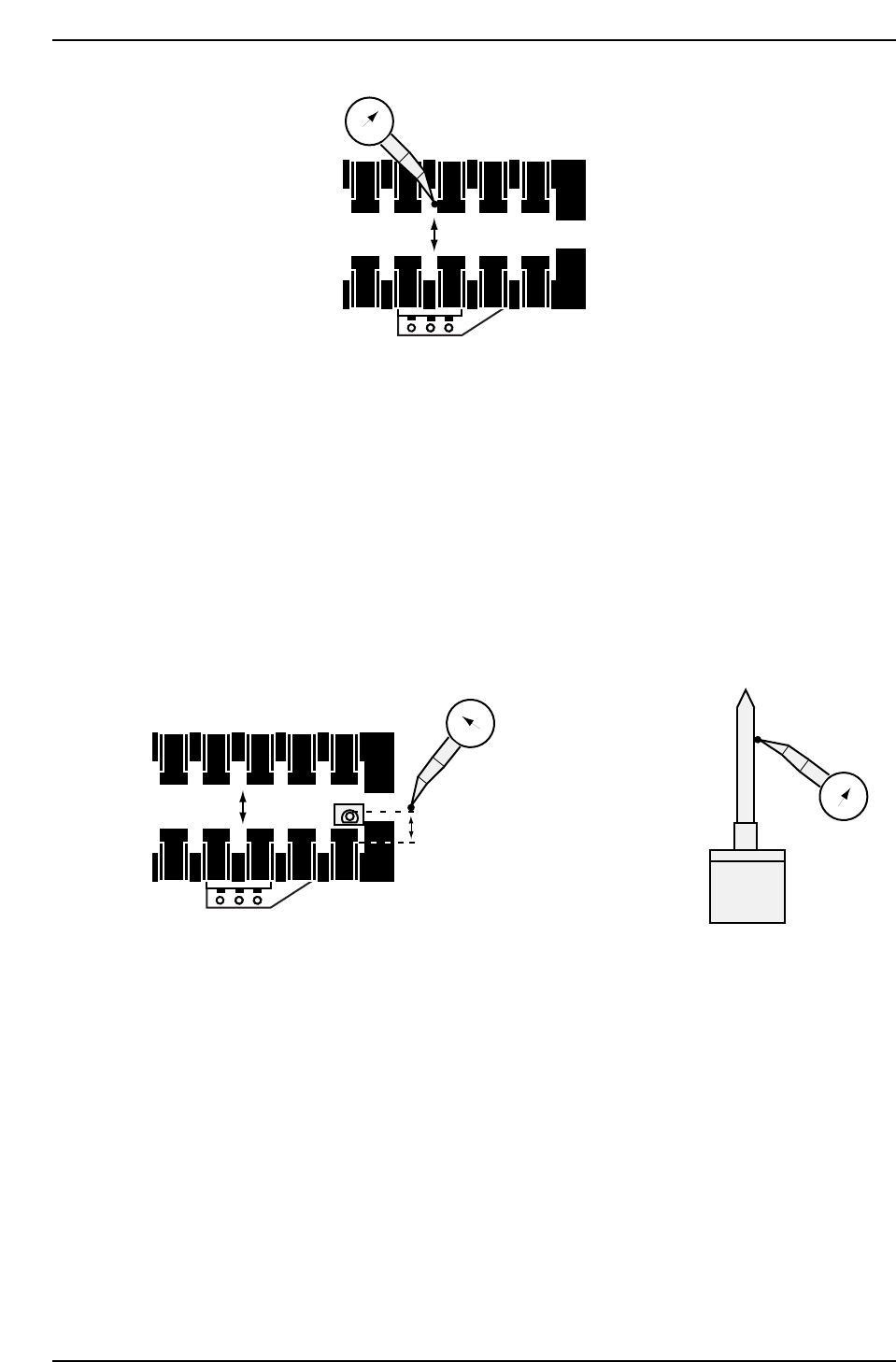
1. Install the refernce tooling pin and spring..
2. Set the dial gauge against the side of the pin on the rear side. Inch
slowly back and forward to find the highest point.
3. Inch the dial gauge until contact is made with the clamper claw. Ensure
the distance is betwen 7 andd 7.2 mm. Adjust the fixed clamper in the Y-
direction while maintaining the linearity.
1.5.8 Claw Fastening
Procedure:
1. Insert a 0.45 mm feeler gauge between the claws and the side of the claw
holders of the two center claws, and a thin feeler gauge such as 0.1 mm
under the claws themselves, hold down and tighten.
2. Finally tighten all the remaining claws.
0
CP7T31023
3500 - 3600 pulses (7 - 7.2 MM)
0
FR
0
CP7T31022
Chapter 1 1.6 Z-Axis Adjustments
Edition 2.0 1-25 CP-7-series Level 3 Tutorial
1.6 Z-Axis Adjustments
Procedure:
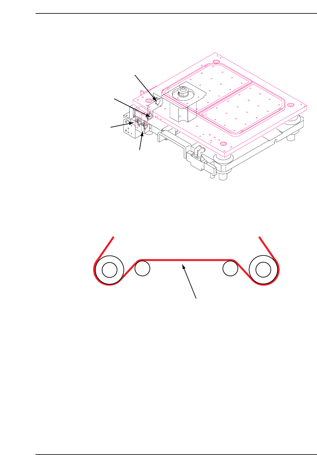
1. Before performing Z-axis adjustments, it is necessary to adjust the Z-axis
timing belt tension. Ensure to adjust where the belt is longest for an
accurate result (see below.)
2. Loosen the bolts which secure the mechanical lock in order to separate
the motor and the table. Verify that neither of the OT sensor beams are
blocked by the dogs.
3. Lower the gain(Pn100) from 70 to30 (CP732E only).
4. Inch or manually adjust the Z-axis to -900 pulses.
Measure here
Tension = 64 ± 2Hz
CP7T31025
CP7T31024
+ OT sensor
(SX019 Z-AXIS +OT)
- OT sensor
(SX01A Z-AXIS -OT)
MOT sensor
(X05E M-LFTR
MIDDLE OT)
Upper end limit
(X05C M-LFTR
UP CHECK)
Chapter 1 1.6 Z-Axis Adjustments
Edition 2.0 1-26 CP-7-series Level 3 Tutorial
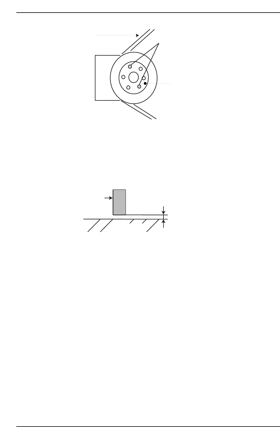
5. Insert a 0.2 mm (100 pulses) feeler gauge under the mechanical stopper
on the front side of the machine, then manually lower the Z-axis until the
stopper makes contact with the feeler gauge. Let the Z-axis rest at the
point at which there is no further movement. Tighten the bolts of the
mechanical lock (Torque = 1 N.m). Remove the feeler gauge and confirm
that the minus mechanical stopper position is -1000 pulses ± 50. Return
the gain setting on the CP-732E to 70.
6. Inch the Z-axis to -500 pulses and adjust the - OT dog to trigger the
sensor at this point.
7. Set the value for -OT as the software limit in the machine’s calibration
data using the following commands:
[MAINTENANCE] → [CALIBRATION] → [TRAVEL LIMITS] → [MIN
LIMIT POS.].
8. Move the XY-table near the OUT loading position and raise the Z-axis
until it reaches the plus mechanical stopper. Confirm that this value is
16850 ~ 17350 pulses (CP-742E(ME): 24200 ~ 24700pulses).
9. Inch the Z-axis to ZL Upper + 300 pulses(CP-742E(ME): 350 pulses)( (see
chapter 2, “Loading Position Adjustments”), and adjust the + OT dog to
activate the sensor at this point. Using the I/O, confirm that the + OT
sensor activates at ZL Upper+ 300 ± 50 pulses (CP-742E(ME): ZL Upper+
350 ± 50 pulses).
10. Move the axis to the point where the + OT sensor activates and set this
value as the software limit in the machine’s calibration data using the
command operation:
[MAINTENANCE] → [CALIBRATION] → [TRAVEL LIMITS] → [MAX
LIMIT POS.].
Stopper
0.2 mm (Using a feeler gauge)
Table bottom
CP7T31027
Insert into either slot
to free span ring
Span Ring
Belt
CP7T31026