CP7 Series Level3 Tutorial Manual.pdf - 第77页
3.2.2 Interference Prevention Sensor Adjustment Procedure: 1. Attach a dial gauge to the edge of the dog as shown below and ensure that the sensor activates when the dog is pushed in 1.5 mm. 2. Inch D2 to 0000 pulses. 3.…
3.2 D-Axis Adjustments
3.2.1 Minus Overtravel Sensor Adjustment
Procedure:
1. Remove both feeder pallets prior to adjusting.
2. Manually move table 2 (table 1) towards the center of the axis to gain
access to the D1 (D2) motor. Remove the two (2) Phillips head screws
securing the cover over the coupling, and take off the cover. Loosen the
for allen bolts securing the coupling.
3. Temporarily remove both minus overtravel dogs, then inch the D1-
motor to 5000 (-5000 for D2) pulses. Push the D1 table against the plus
mechanical stopper (D2 against the minus mechanical stopper), and
tighten the coupling. D-axis coupling torque = M5: 8.3 N.m, M4: 4 Nm.
(CP-742E(ME): all 8.3 N.m).
4. Push the EMERGENCY STOP button, and pull the D1 (D2) table back
against the stopper again. Record the motor pulse count at this point.
5. Replace the -OT dog and adjust to activate the sensor at the point 3500
pulses back from the stopper. Record the counter value.
6. Move back an additional 500 pulses from the position at which the
minus OT sensor activates and set this position in calibration data as the
D1 Max Limit Pos (D2: Min Limit Pos). using the following commands:
[MAINTENANCE] → [CALIBRATION] → [TRAVEL LIMITS] → [MAX
LIMIT POS.] (D2: [MIN LIMIT POS]).
7. Confirm the sensor reaction using the I/O commands:
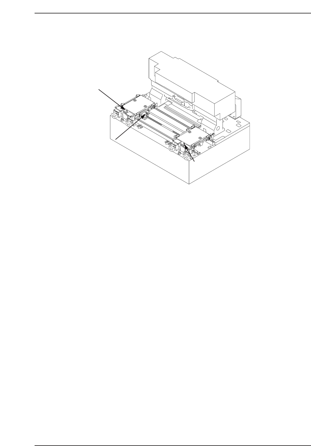
SX042 D1 AXIS -OT
SX04A D2 AXIS -OT
D1 - OT sensor
(SX042 D1-AXIS -OT)
D2 -OT sensor
(SX04A D2-AXIS -OT)
Interference prevention
sensor
(SX041 D1-AXIS +OT/
SX049 D2-AXIS +OT)
Table 1
Table 2
CP7T33004
Chapter 3 3.2 D-Axis Adjustments
Edition 2.0 3-5 CP-7-series Level 3 Tutorial
3.2.2 Interference Prevention Sensor Adjustment
Procedure:
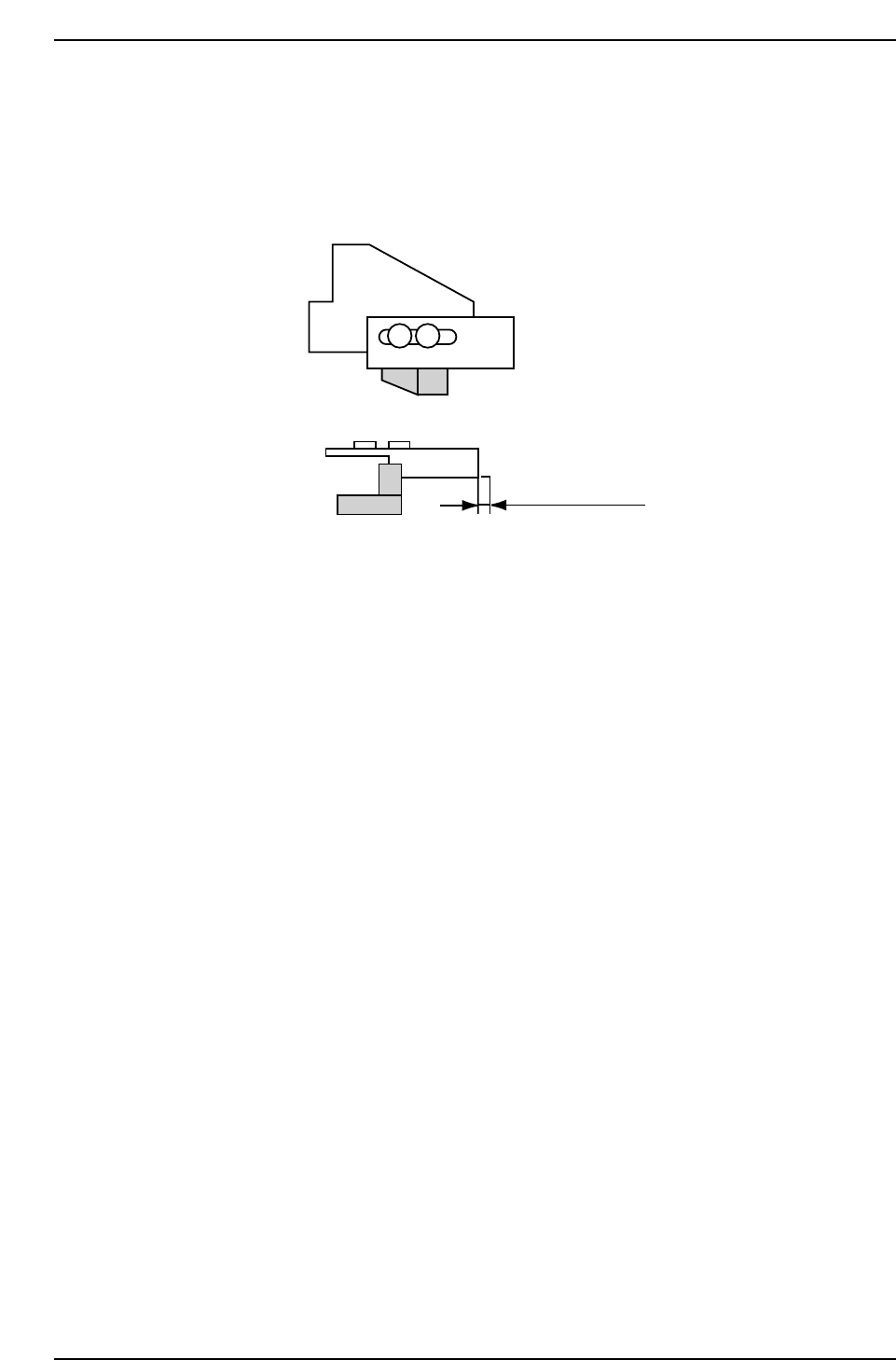
1. Attach a dial gauge to the edge of the dog as shown below and ensure
that the sensor activates when the dog is pushed in 1.5 mm.
2. Inch D2 to 0000 pulses.
3. Inch D1 against the stopper i.e. towards D2 until the interference sensor
(SX041) just comes on. Record the pulse count for D1. Move back 500
pulses from this position,and set this as the travel limit in calibrationdata
using the following commands:
[MAINTENANCE] → [CALIBRATION] → [TRAVEL LIMITS] →
MINIMUM LIMIT D1].
Note: For the CP-732E, push the D1 table against the D2 stopper, then move back and the
confirm that the interference prevention sensor activates at 1000 ± 500 pulses from the
D2-table stopper. Inch back a further 500 pulses from the point of activation and record
this value in calibration data using the same commands as for CP-742E(ME).
4. Move the D1-axis to its retract position (0 pulses).
5. Inch the D2 axis in the direction of the D1-table until the interference
prevention sensor just comes on. Record the pulse count and inch the
D2-table 500 pulses back from this position. Set this as the travel limit in
calibration data using the following commands:
[MAINTENANCE] → [CALIBRATION] → [TRAVEL LIMITS] →
[MAXIMUM LIMIT D1].
Note: For the CP-732E, push the D2-table against the D1 stopper, then move back and the
confirm that the interference prevention sensor activates at 1000 ± 500 pulses from the
D1-table stopper. Inch back a further 500 pulses from the point of activation and record
this value in calibration data using the same commands as for CP-742E(ME).
6. If accurately adjusted, the distance from the center of slot 70/40 (D1) to
slot 1 (D2) should be 72 mm for the CP742E(ME), and the distance from
slot 30 (D1) to the center of slot 1 on D2 should be 59 mm.
About 1.5 mm
CP7T33005
Chapter 3 3.2 D-Axis Adjustments
Edition 2.0 3-6 CP-7-series Level 3 Tutorial
3.2.3 Pick-up Position Adjustment (T1, T2)
Pick-up position T1 (T2) is the amount of D-axis movement required to move
the first feeder location of each table to align an 8 mm tape feeder to the pick-
up nozzle at station 1.
An incorrect value for pick-up position will result in poor pick-up or nozzle damage.
Procedure:
1. Insert the pick-up position jig in slot 1 on device pallet 1. Remove the
nozzle holder from Head A and attach the centering jig.
2. Activate the pick-up solenoid and inch Head A to station 1, 170°.
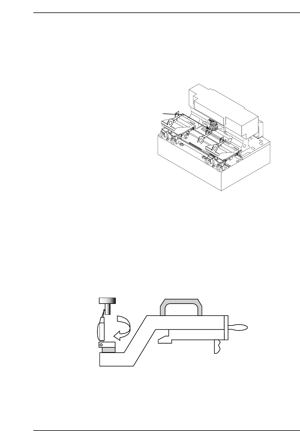
3. Inch the jig at feeder slot 1 to the pick-up position and set the dial gauge
needle against the surface of the centering jig.
4. Zero the dial gauge and rotate around the centering jig as shown below.
Inch the pallet in the left and right direction until the dial gauge reads
zero on both sides of the jig. Repeat for T2 on pallet 2.
5. Register the pick-up positions in the machine calibration data using
the following commands:
[MAINTENANCE] - [CALIBRATION] - [PICK-UP REFERENCE].
CP7T33007
T1: Distance from feeder in retract
position to pick-up at station 1
CP7T33006
Chapter 3 3.2 D-Axis Adjustments
Edition 2.0 3-7 CP-7-series Level 3 Tutorial