CP7 Series Level3 Tutorial Manual.pdf - 第105页
Notes: Chapter 5 5.2 NC-Axis Adjustments Edition 2.0 5-6 CP-7-series Level 3 T utorial
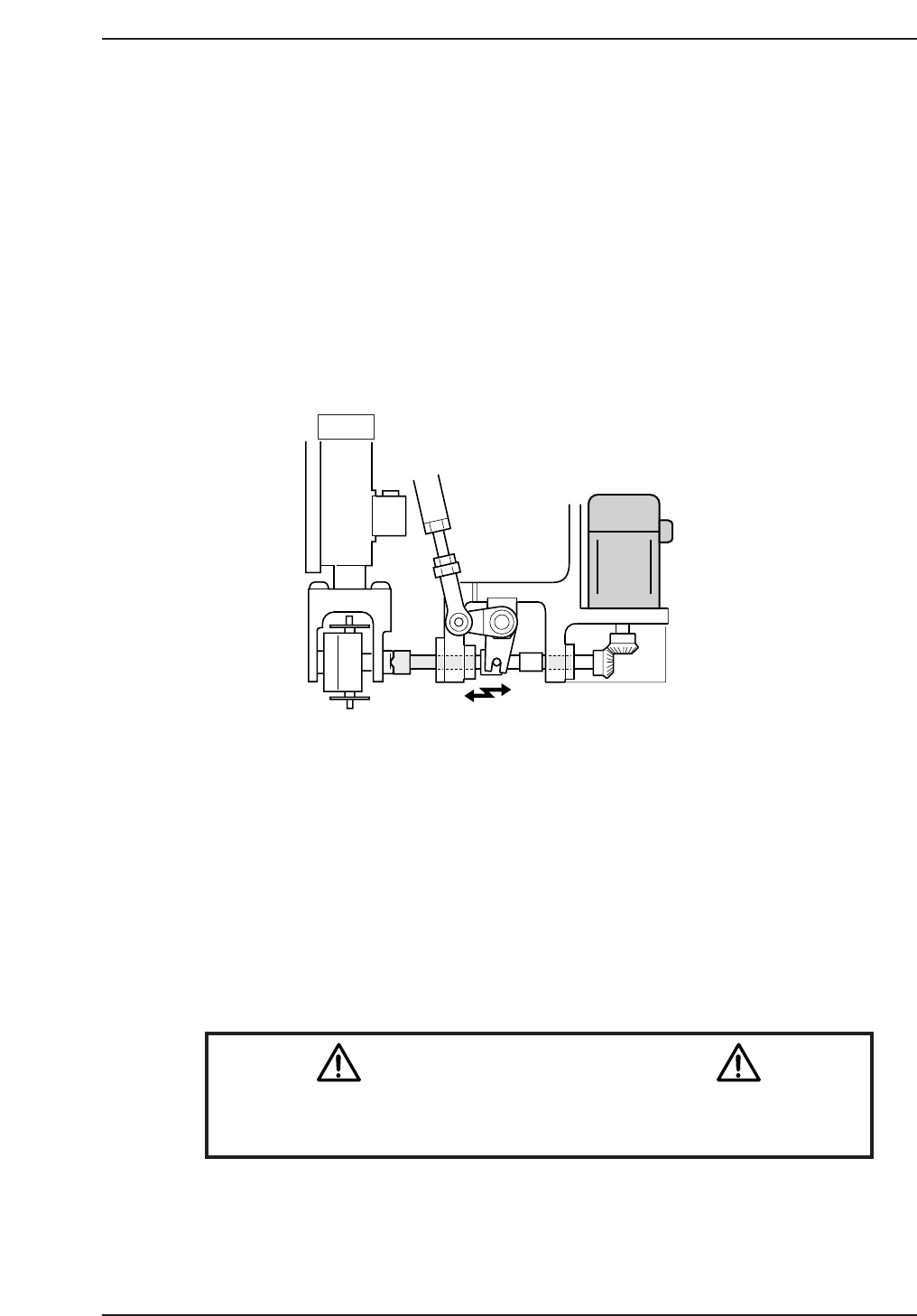
5.2 NC-Axis Adjustments
5.2.1 NC Origin Position
Procedure:
1. Rotate the cam angle to 0°.
2. Activate the nozzle change solenoid valve at the I/O: Y037 NOZZLE
CHANGE SOL ENGAGED.
3. Push the EMERGENCY STOP button to cut the 200V power supply to
the machine and rotate the cam to 141°.
4. Engage the NC clutch rotor with the nozzle holder clutch while holding
the clutch horizontal.
5. Rotate the cam to a position where the clutch starts to engage and where
the backlash decreases for the NC clutch rotation.
6. Rotate the motor gear and note the range of backlash. Take the center
value and set this as the NC origin using the following command:
[MAINTENANCE] → [CALIBRATION] → [ORIGIN POS. OFFSET] →
[SET (NC)].
The resultant value should be no more than ±1800 pulses.
Caution
Ensure that new Calibration data is backed-up to the host computer
once the adjustment procedure is complete.
CN002
14 st
CP7T35005
Chapter 5 5.2 NC-Axis Adjustments
Edition 2.0 5-5 CP-7-series Level 3 Tutorial

Notes:
Chapter 5 5.2 NC-Axis Adjustments
Edition 2.0 5-6 CP-7-series Level 3 Tutorial

5.3 Training Evaluation
Circle the most appropriate answer from the list below.
(1) The nozzle alignment adjustment should be performed at what angle?
a. 180°
b. 200°
(2) The backlash for the nozzle changer gears should be in the range:
a. 0.3 to 1.3 mm
b. 0.03 to 0.13 mm
(3) At what angle should the NC origin position be calculated?
a. 128°
b. 141°
(4) Which of the following would be the result of an incorrectly adjusted NC
origin position?
a. A station 15 error.
b. Low placing accuracy.
Chapter 5 5.3 Training Evaluation
Edition 2.0 5-7 CP-7-series Level 3 Tutorial