CP7 Series Level3 Tutorial Manual.pdf - 第37页
Chapter 1 1.3 Replacing the Y -Motor Edition 2.0 1-12 CP-7-series Level 3 T utorial 1.3.2 Installing the Y -Axis Motor Procedure: 1. Secure a new motor to the machine with the four (4) allen bolts. 2. Reconnect the two (…
Chapter 1 1.3 Replacing the Y-Motor
Edition 2.0 1-11 CP-7-series Level 3 Tutorial
1.3.1 Removing the Y-Axis Motor
Procedure:
1. Turn OFF the machine power.
2. Remove the front cover from the machine in order to gain access to the
motor.
3. Retract both the IN and OUT carriers, and widen the machine’s conveyor
rails to allow better access to the machine.
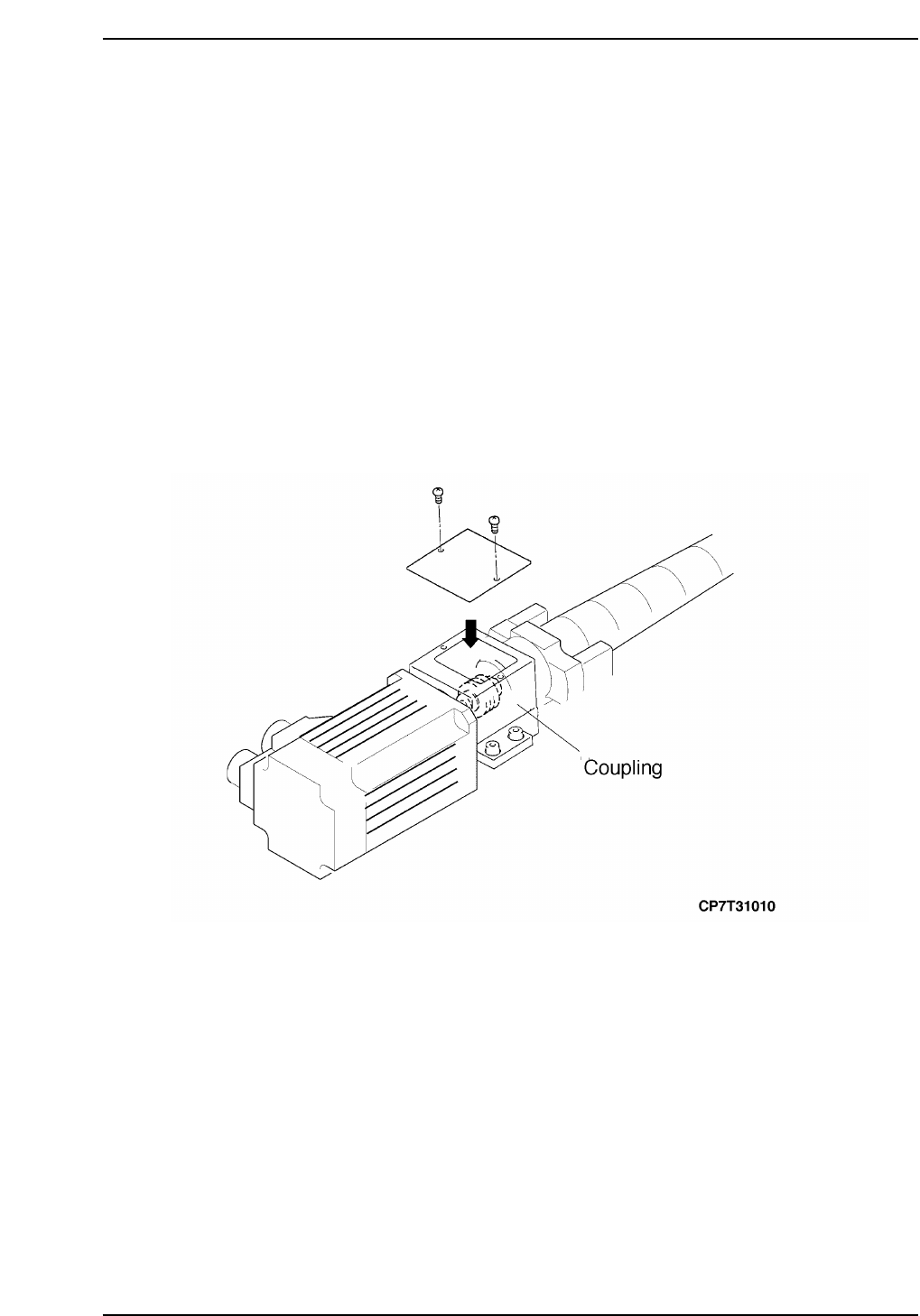
4. Push the motor away from the stopper and remove the two (2) Phillips
head screws securing the cover over the coupling.
5. Loosen the coupling on the motor side to separate the motor from the
ball screw (refer to the figure below).
6. Disconnect the two (2) electrical connections from the motor.
7. Remove the four (4) allen extension bolts securing the motor to the
machine and then remove the motor.

Chapter 1 1.3 Replacing the Y-Motor
Edition 2.0 1-12 CP-7-series Level 3 Tutorial
1.3.2 Installing the Y-Axis Motor
Procedure:
1. Secure a new motor to the machine with the four (4) allen bolts.
2. Reconnect the two (2) electrical connectors to the motor.
Note: Do not tighten the coupling at this stage.
Notice
Note that as the CP-7 utilizes absolute encoders on all axes, it is no
longer necessary to boot up the machine in Mechacheck mode when
performing motor adjustments.
N001
Chapter 1 1.4 Y-Axis Adjustments
Edition 2.0 1-13 CP-7-series Level 3 Tutorial
1.4 Y-Axis Adjustments
Procedure:
1. Ensure that the Y-axis is not inclined or tilted.
2. Either manually, or by means of the inching keys, move the motor until
the motor pulse count reads 75000 pulses (CP-742E(ME): 110000).
Note: It is necessary to offset by 75000(110,000) pulses in order to achieve the desired result at
stage 5.
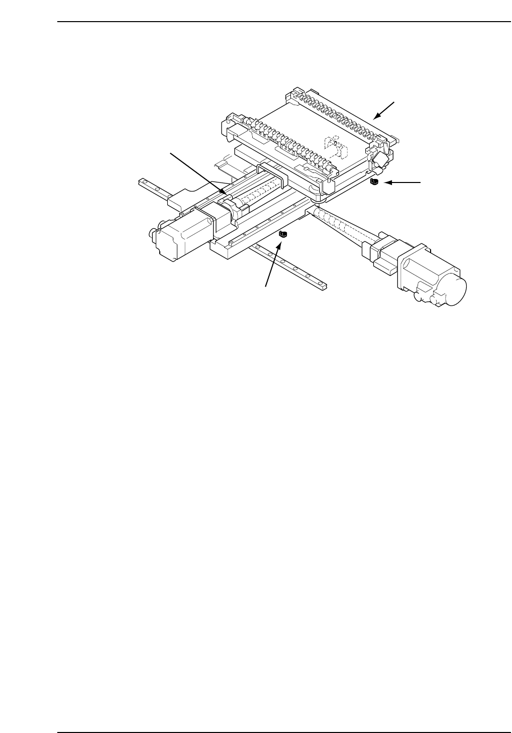
3. Place the 155 mm spacer between the Y-axis minus mechanical stopper
and the Y-axis base (refer to the diagram opposite). At this point, tighten
the coupling bolts with 3.4 N.m torque (CP742E(ME): 8 N.m).
4. Push the EMERGENCY STOP button and pull the XY-table back against
the minus stopper. Record the motor pulse count at this point. The
counter should read -2500 ± 100.
5. Adjust the - OT dog so that the sensor activates when the Y-axis is
moved back 2000 pulses from the mechanical stopper. Take a note of the
motor pulse count at this point.
6. Move the Y-axis back 500 pulses from the above noted position and set
this value as the software limit in the machine’s calibration data using
the command operation:
[MAINTENANCE] → [CALIBRATION] → [TRAVEL LIMITS] → [MIN
LIMIT POS.].
7. Push the XY-table to the plus side mechanical stopper and record the
motor pulse count.
CP7T31011
- OT sensor
(SX012 Y-AXIS -OT)
+ OT sensor
(SX011 Y-AXIS +OT)
+ Mechanical stopper
- Mechanical stopper