CP7 Series Level3 Tutorial Manual.pdf - 第48页
Chapter 1 1.5 Replacing the Z-Motor Edition 2.0 1-23 CP-7-series Level 3 T utorial 6. Inch to point C. If out by 0.1 mm or more, holding the rail at C, push until the dial gauge reads zero and partially tighten the allen…
Chapter 1 1.5 Replacing the Z-Motor
Edition 2.0 1-22 CP-7-series Level 3 Tutorial
5. Move the adjustable rail back 180 mm from the fixed rail and measure at
points 4, 5 and 6. Finally, repeat for points 7, 8 and 9 at 250 mm from the
fixed rail.
6. Ensure that points 1, 3, 7, 9, 10 and 12 are within range.
7. To adjust, move the adjustable rail back to 180 mm and use the lock nut
jig and allen wrench to raise or lower the two rear corners until both
points 4 and 6 fall within or up to 0 ± 0.1 mm from point 1.
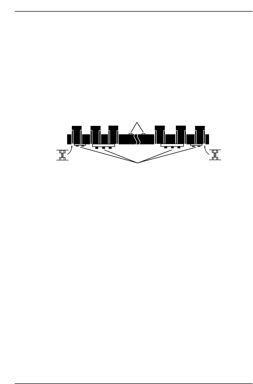
8. Raise and lower the fixed rail using the two (2) adjustment bolts as
shown in the diagram below.
9. Total tolerance for the whole board is 0.15 mm (if possible 0.1 mm).
1.5.5 Fixed Rail Linearity
Once the table top and clamper parallelism adjustments have been carried out, confirm
and if necessary, adjust the linearity of the fixed rail. Failure to straighten the rail within
permissible limits will result in clamping problems or skewed PCBs.
Procedure:
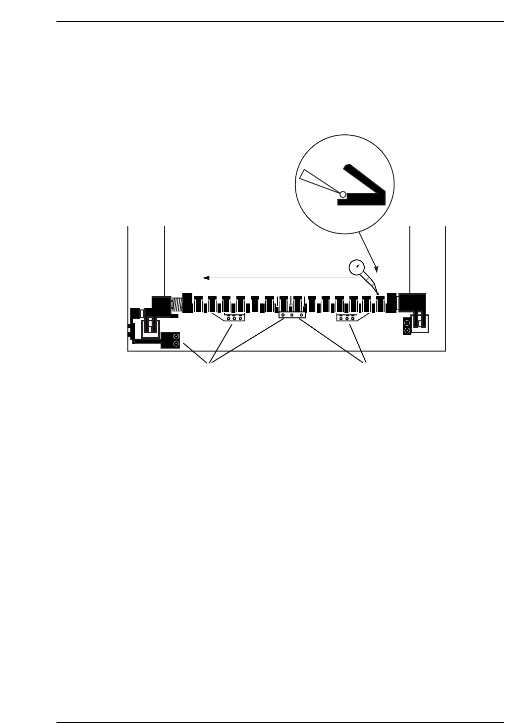
1. With all the clamper claws on the fixed rail open, position the dial on the
vertical edge of the clamper claw at position A (refer to diagram on the
opposite page).
2. Set the dial gauge to zero and inch in the X-direction at 1% inching speed
to position B. Note the dial gauge reading.
3. Inch from position B to position C and note the dial gauge reading. The
dial gauge should show no more than a 0.1 mm deflection at either point.
4. If the dial gauge deflection exceeds the permissible tolerance, loosen all
bolts as shown in the diagram opposite.
5. Again, zero the dial gauge at position A, and inch to position B. If the
deflection exceeds 0.1 mm, tap lightly on the clamper at point C until the
dial gauge registers zero. Zero again at point A, and inch to B. If at zero,
partially tighten the allen bolts at point E and F.
Loosen all ten bolts
Fixed rail height
adjustment bolt
Fixed rail height
adjustment bolt
CP7T31020
Loosen two bolts
on rear side
Chapter 1 1.5 Replacing the Z-Motor
Edition 2.0 1-23 CP-7-series Level 3 Tutorial
6. Inch to point C. If out by 0.1 mm or more, holding the rail at C, push
until the dial gauge reads zero and partially tighten the allen bolts at
point G and H.
7. Zero the dial again at position A and repeat the measurement. If all
values are within the tolerance, fully tighten all bolts and finally recheck.
1.5.6 X-Direction Clamper Linearity
Procedure:
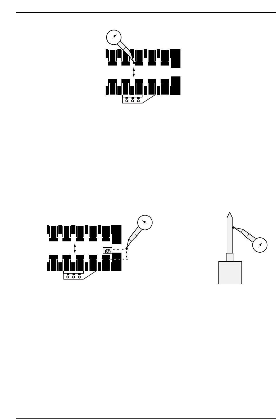
1. Place the dial gauge against the side of one of the clamper claws on the
movable side and set to zero (refer to diagram on opposite page).
2. Inch in the X-axis till the dial reaches the same position on the fixed
clamper claw and note the dial gauge reading. The maximum
permissible tolerance is 0.2 mm.
3. If outside the range, attach a dial gauge to the front left and right hand
sides of the XY-table, set to zero, and loosen the 13 bolts noted in the
previous diagram.
Note: The dial gauges are used to ensure that the results of the previous adjustment are not
affected.
4. With dial gauge against the side of the claw on the fixed side, lightly tap
the clamper in the X-direction until the dial gauge reads zero, while
ensuring that the readings on both dials on the XY-table still read zero.
CP7T31021
Loosen Loosen
0
A
BC
XY-table
E
F
D
G
H
Chapter 1 1.5 Replacing the Z-Motor
Edition 2.0 1-24 CP-7-series Level 3 Tutorial
5. Tighten all bolts and recheck.
6. Finally, tighten all the clamper claws, ensuring a gap of at least 0.1 mm.
1.5.7 Reference Pin Adjustment
Procedure:
1. Install the refernce tooling pin and spring..
2. Set the dial gauge against the side of the pin on the rear side. Inch
slowly back and forward to find the highest point.
3. Inch the dial gauge until contact is made with the clamper claw. Ensure
the distance is betwen 7 andd 7.2 mm. Adjust the fixed clamper in the Y-
direction while maintaining the linearity.
1.5.8 Claw Fastening
Procedure:
1. Insert a 0.45 mm feeler gauge between the claws and the side of the claw
holders of the two center claws, and a thin feeler gauge such as 0.1 mm
under the claws themselves, hold down and tighten.
2. Finally tighten all the remaining claws.
0
CP7T31023
3500 - 3600 pulses (7 - 7.2 MM)
0
FR
0
CP7T31022