CP7 Series Level3 Tutorial Manual.pdf - 第33页
Notes: Chapter 1 1.2 X-Axis Adjustments Edition 2.0 1-8 CP-7-series Level 3 T utorial
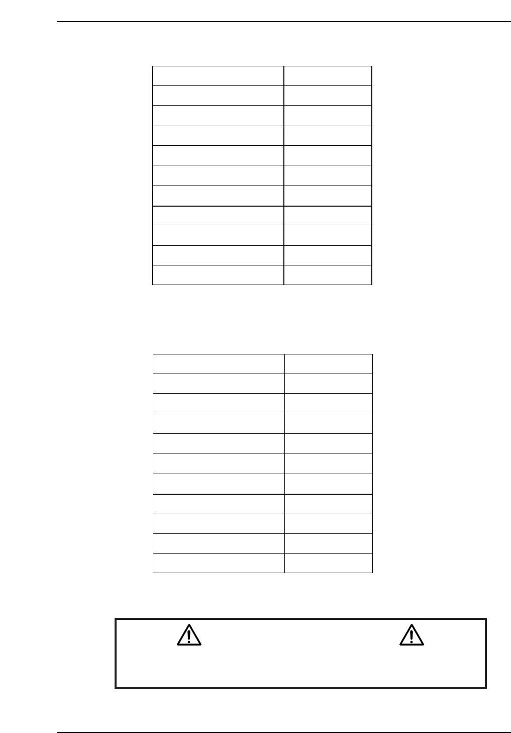
CP-732E Calibration Data Servo Count Chart (X-axis)
CP-742E(ME) Calibration Data Servo Count Chart (X-axis)
Caution
Ensure that new Calibration data is backed-up to the host computer
once the adjustment procedure is complete.
CN002
Plus Mechanical stopper
- OT sensor
Max limit pos. X
Loading pos. XL OUT
PCB check pos. X
Mark read pos. Xc
Loading pos. XL IN
Placing pos. Xø
Min limit pos. X
+ OT sensor
Minus mechanical stopper
2500 ± 100
500 ± 100
0 ± 100
-11250
-190000
-231000
-271000
-270500
-275500 ± 1000
-276000 ± 1000
-278000
CP7T31007
± 1000
Plus Mechanical stopper
- OT sensor
Max limit pos. X
Loading pos. XL OUT
PCB check pos. X
Mark read pos. Xc
Loading pos. XL IN
Placing pos. Xø
Min limit pos. X
+ OT sensor
Minus mechanical stopper
2500 ± 100
500 ± 100
0 ± 100
-11250
-140000
-180500
-220500
-222500
-225000 ± 1000
-225500 ± 1000
-227500 ± 1000
CP7T31006
Chapter 1 1.2 X-Axis Adjustments
Edition 2.0 1-7 CP-7-series Level 3 Tutorial

Notes:
Chapter 1 1.2 X-Axis Adjustments
Edition 2.0 1-8 CP-7-series Level 3 Tutorial
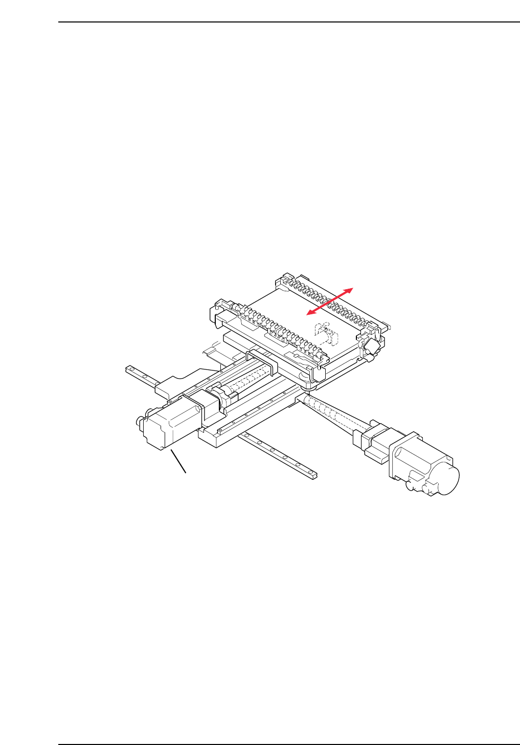
1.3 Replacing the Y-Motor
The Y-motor (refer to figure below) is responsible for moving the production table
to the front and rear inside the machine (as viewed from the front of the machine).
This allows the PCB to be accurately positioned underneath the placing heads for
part placement.
A poorly adjusted or problematic Y-axis will result in placement offset in the up
and down direction. Recalibration of the Y-axis is needed to eradicate this
problem.
• Damage or slippage of the coupling that connects the Y-motor and the Y-axis ball
screw.
• After replacing the Y-motor
• After replacing the OT sensors, etc.
CP7T31008
Y-axis motor
Chapter 1 1.3 Replacing the Y-Motor
Edition 2.0 1-9 CP-7-series Level 3 Tutorial