CP7 Series Level3 Tutorial Manual.pdf - 第39页
Chapter 1 1.4 Y -Axis Adjustments Edition 2.0 1-14 CP-7-series Level 3 T utorial 8. Adjust the sensor position to activate when the Y-axis moves 500 pulses back from the stopper. Record the motor pulse count at this time…
Chapter 1 1.4 Y-Axis Adjustments
Edition 2.0 1-13 CP-7-series Level 3 Tutorial
1.4 Y-Axis Adjustments
Procedure:
1. Ensure that the Y-axis is not inclined or tilted.
2. Either manually, or by means of the inching keys, move the motor until
the motor pulse count reads 75000 pulses (CP-742E(ME): 110000).
Note: It is necessary to offset by 75000(110,000) pulses in order to achieve the desired result at
stage 5.
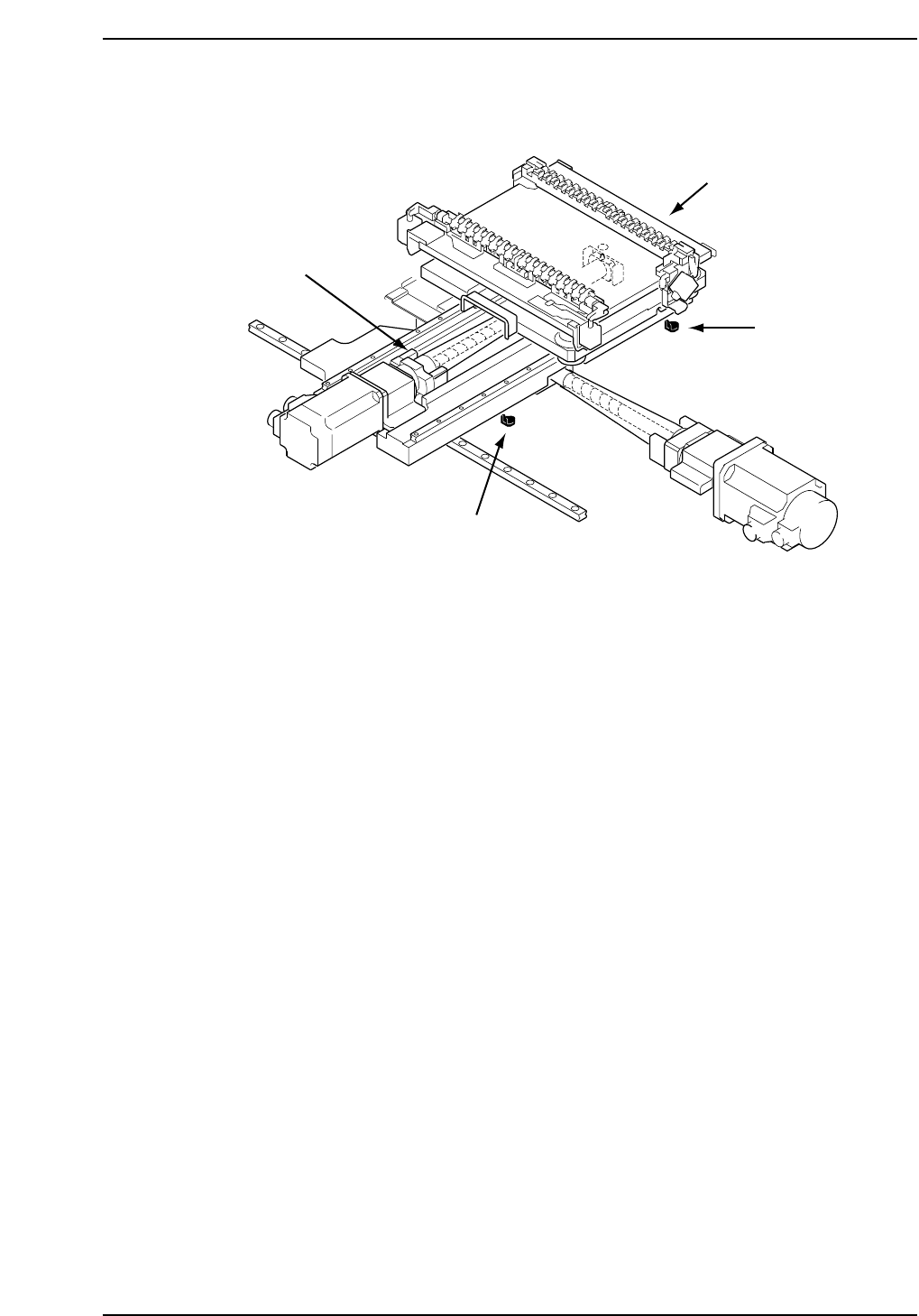
3. Place the 155 mm spacer between the Y-axis minus mechanical stopper
and the Y-axis base (refer to the diagram opposite). At this point, tighten
the coupling bolts with 3.4 N.m torque (CP742E(ME): 8 N.m).
4. Push the EMERGENCY STOP button and pull the XY-table back against
the minus stopper. Record the motor pulse count at this point. The
counter should read -2500 ± 100.
5. Adjust the - OT dog so that the sensor activates when the Y-axis is
moved back 2000 pulses from the mechanical stopper. Take a note of the
motor pulse count at this point.
6. Move the Y-axis back 500 pulses from the above noted position and set
this value as the software limit in the machine’s calibration data using
the command operation:
[MAINTENANCE] → [CALIBRATION] → [TRAVEL LIMITS] → [MIN
LIMIT POS.].
7. Push the XY-table to the plus side mechanical stopper and record the
motor pulse count.
CP7T31011
- OT sensor
(SX012 Y-AXIS -OT)
+ OT sensor
(SX011 Y-AXIS +OT)
+ Mechanical stopper
- Mechanical stopper
Chapter 1 1.4 Y-Axis Adjustments
Edition 2.0 1-14 CP-7-series Level 3 Tutorial
8. Adjust the sensor position to activate when the Y-axis moves 500 pulses
back from the stopper. Record the motor pulse count at this time, and
adjust the +OT sensor to trigger at this point.
9. Move the Y-axis back 500 pulses from the above noted position and set
this value as the software limit in the machine’s calibration data using
the command operation:
[MAINTENANCE] → [CALIBRATION] → [TRAVEL LIMITS] → [MAX
LIMIT POS.].
Note: Be careful when adjusting the CP-742ME Y-axis as the distance between the (+)
mechanical stopper and the (+) OT sensor is only 500 pulses.
10. Confirm the above adjustments at the I/O using the following
commands:
[MAINTENANCE] → [I/O CHECK] → [SERVO] → [INPUT].
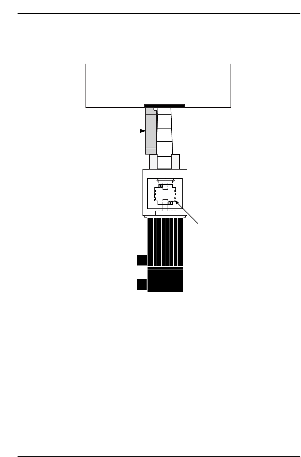
X011 Y AXIS +OT
X012 Y AXIS -OT
XY-table
155 mm spacer
Y-motor
CP7T31012
Y-axis coupling
Chapter 1 1.4 Y-Axis Adjustments
Edition 2.0 1-15 CP-7-series Level 3 Tutorial
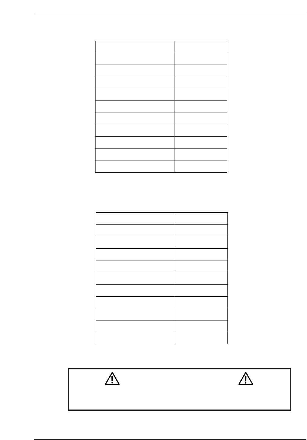
CP-732E Calibration Data Servo Count Chart (Y-axis)
CP-742E(ME) Calibration Data Servo Count Chart (Y-axis)
Caution
Ensure that new Calibration data is backed-up to the host computer
once the adjustment procedure is complete.
CN002
Plus mechanical stopper
+ OT sensor
Max limit pos.Y
Placing pos. Yø
Mark read pos. Yc
PCB check pos. Y
Loading pos. YL IN
Loading pos. YL OUT
Min limit pos. Y
- OT sensor ON
Minus mechanical stopper
241500 ± 1000
241000 ± 1000
240500 ± 1000
238500
226000
205000
2500
2500
0 ± 100
-500 ± 100
-2500 ± 100
CP7T31014
Plus mechanical stopper
+ OT sensor
Max limit pos.Y
Placing pos. Yø
Mark read pos. Yc
PCB check pos. Y
Loading pos. YL IN
Loading pos. YL OUT
Min limit pos. Y
- OT sensor ON
Minus mechanical stopper
195000 ± 1000
193000 ± 1000
192500 ± 1000
190000
175000
160000
2500
2500
0 ± 100
-500 ± 100
-2500 ± 100
CP7T31013