CP7 Series Level3 Tutorial Manual.pdf - 第129页
8.1.1 Parts Camera Removal Procedure: 1 . With the machine powered OFF, remove the video cables from the cameras as shown below. 2. Remove the four (4) CCD mounting bolts from the right hand side of the bracket and caref…
Affected Calibration data: Wide Camera Pixel Size X → MC0WCPX
Wide Camera Pixel Size Y → MC0WCPY
Wide Camera Rotation → MC0WCR
Narrow Camera Pixel Size X → MC0NCPX
Narrow Camera Pixel Size X → MC0NCPY
Narrow Camera Rotation → MC0NCR
Caution
Ensure that a back-up of calibration data is taken prior to adjusting the
cameras.
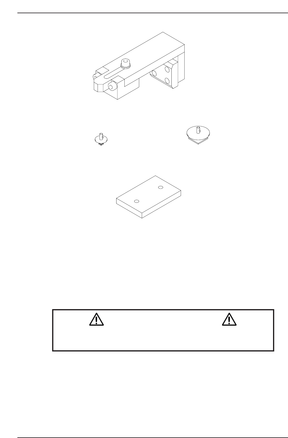
CN004
Inspection jig ADCPJ8100Inspection jig ADCPJ8110
10st cam lever spring stopper jig
XY Magnet stand Z9326DCPJ3180
CP7T38002
Chapter 8 8.1 Parts Cameras
Edition 2.0 8-2 CP-7-series Level 3 Tutorial
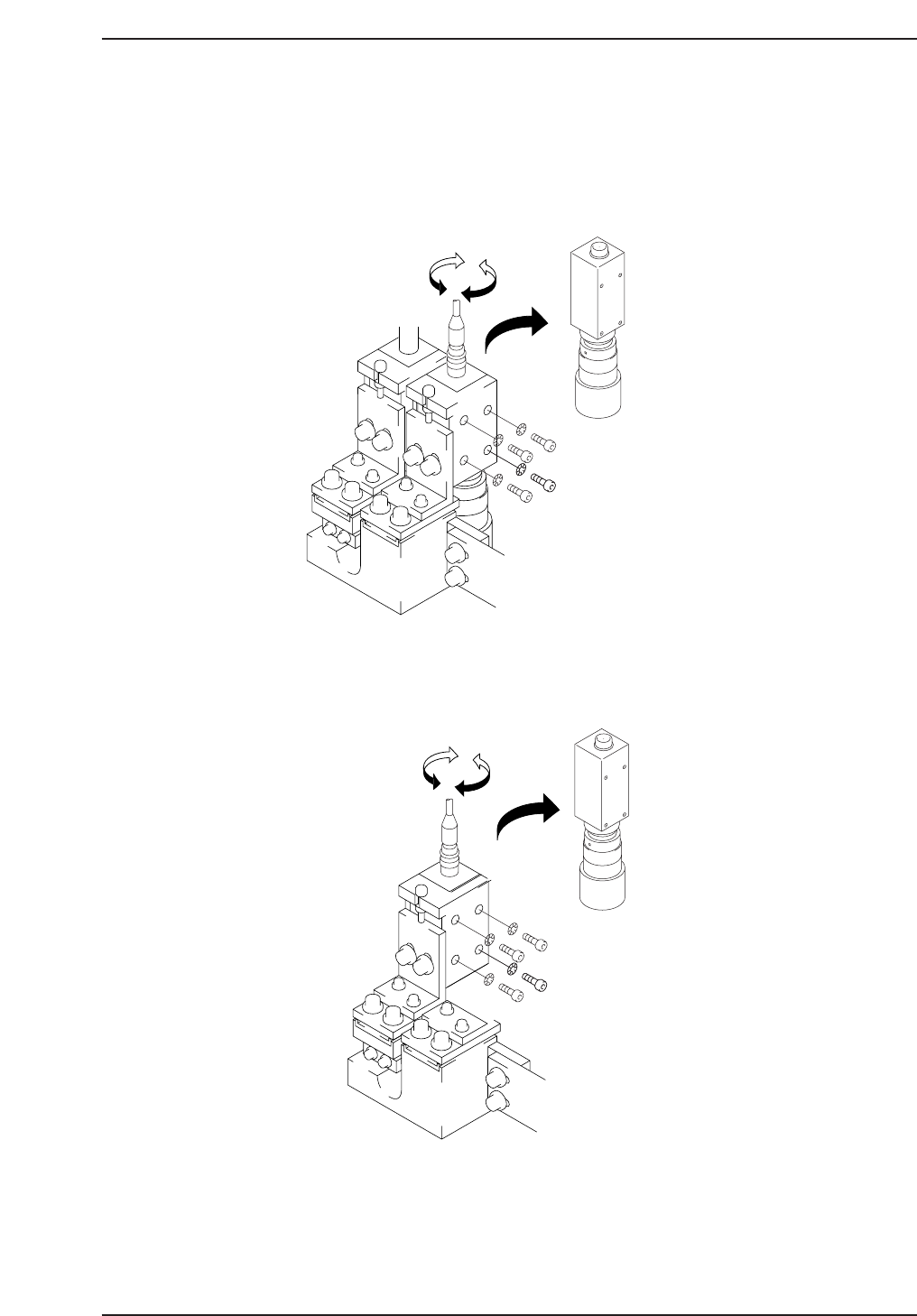
8.1.1 Parts Camera Removal
Procedure:
1. With the machine powered OFF, remove the video cables from the
cameras as shown below.
2. Remove the four (4) CCD mounting bolts from the right hand side of the
bracket and carefully remove the cameras.
3. Remove the lens assembly from the CCD module using the appropriate
size allen wrench.
Narrow
CP7T38004
Wide
CP7T38003
Chapter 8 8.1 Parts Cameras
Edition 2.0 8-3 CP-7-series Level 3 Tutorial
8.1.2 Parts Camera Installation
Procedure:
1. Ensure to make the following amplifier and aperture settings prior to
returning the cameras to the machine.
2. Install the lens assembly to the new CCD module and remount the unit
with the two (2) mounting bolts.
3. Reconnect the video cable to the camera unit.
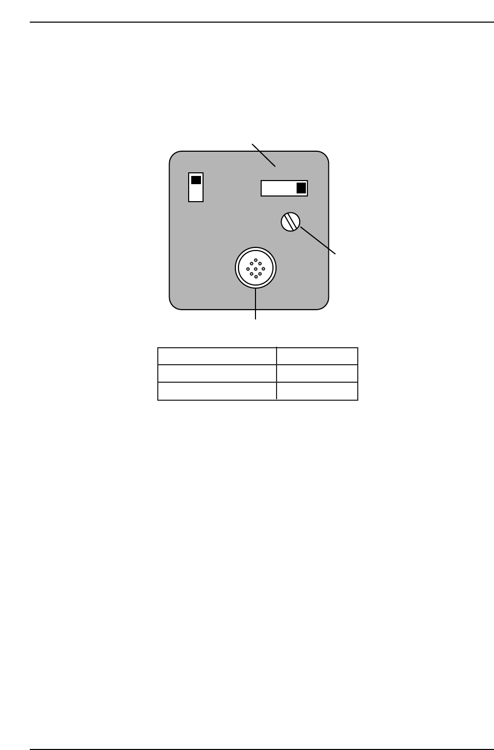
SIGNAL
AFM
1N
1l
Power/Video connector
Gain switch
Manual Gain adj. trimmer
Camera
Apperture
Narrow
Wide
2
2.8
CP7T38005
Chapter 8 8.1 Parts Cameras
Edition 2.0 8-4 CP-7-series Level 3 Tutorial