CP7 Series Level3 Tutorial Manual.pdf - 第31页
Note: In the case of the CP-742E(ME), it is not necessary to use a jig. After loosening the coupling, inch the motor to 2500 pulses, push the table against the stopper and tighten the coupling bolts with 14 N.m torque. C…
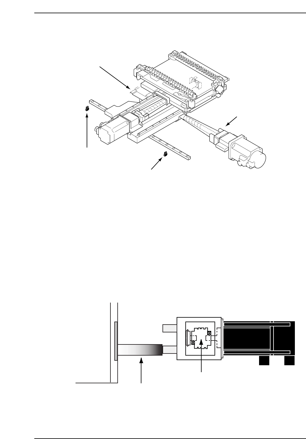
1.2 X-Axis Adjustments
Procedure:
CP732E Only
1. Temporarily remove the -OT sensor dog prior to performing the X-axis
adjustments.
2. Either manually, or by means of the inching keys, move the motor until
the pulse count reads -75000 pulses.
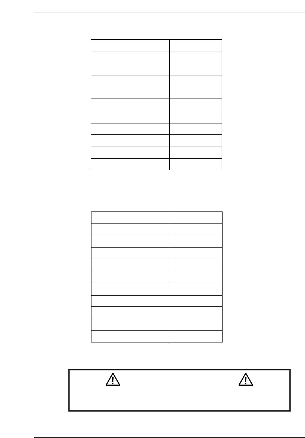
3. Place the 155 mm spacer between the X-axis plus mechanical stopper and
the X-axis base (refer to the diagram below). At this point, tighten the
coupling bolts with 7 N.m torque.
4. Remove the spacer and push the X-axis against the plus side mechanical
stopper. Record the motor pulse count at this position.
XY-table
155 mm spacer
X-motor
CP7T31005
X-axis coupling
CP7T31004
- OT sensor
(SX00A X-AXIS -OT)
+ OT sensor
(SX009 X-AXIS +OT)
+ Mechanical stopper
- Mechanical stopper
Chapter 1 1.2 X-Axis Adjustments
Edition 2.0 1-5 CP-7-series Level 3 Tutorial

Note: In the case of the CP-742E(ME), it is not necessary to use a jig. After loosening the
coupling, inch the motor to 2500 pulses, push the table against the stopper and tighten
the coupling bolts with 14 N.m torque.
CP-7-series
5. Adjust the - OT dog to activate the sensor when the X-axis is moved back
2000 pulses from the stopper. Record the motor pulse count at this
position.
6. Move the X-axis back 500 pulses from the above noted position and set
this value as the software limit in the machine’s calibration data using
the command operation:
[MAINTENANCE] → [CALIBRATION] → [TRAVEL LIMITS] → [MAX
LIMIT POS.].
7. Push the table against the minus side mechanical stopper and record the
motor pulse count at this position.
8. Adjust the + OT dog to activate the sensor when the X-axis is moved
back 2000 pulses from the stopper. Record the motor pulse count at this
position.
9. Move the X-axis back 500 pulses from the above noted position and set
this value as the software limit in the machine’s calibration data using
the command operation:
[MAINTENANCE] → [CALIBRATION] → [TRAVEL LIMITS] → [MIN
LIMIT POS.].
Chapter 1 1.2 X-Axis Adjustments
Edition 2.0 1-6 CP-7-series Level 3 Tutorial
CP-732E Calibration Data Servo Count Chart (X-axis)
CP-742E(ME) Calibration Data Servo Count Chart (X-axis)
Caution
Ensure that new Calibration data is backed-up to the host computer
once the adjustment procedure is complete.
CN002
Plus Mechanical stopper
- OT sensor
Max limit pos. X
Loading pos. XL OUT
PCB check pos. X
Mark read pos. Xc
Loading pos. XL IN
Placing pos. Xø
Min limit pos. X
+ OT sensor
Minus mechanical stopper
2500 ± 100
500 ± 100
0 ± 100
-11250
-190000
-231000
-271000
-270500
-275500 ± 1000
-276000 ± 1000
-278000
CP7T31007
± 1000
Plus Mechanical stopper
- OT sensor
Max limit pos. X
Loading pos. XL OUT
PCB check pos. X
Mark read pos. Xc
Loading pos. XL IN
Placing pos. Xø
Min limit pos. X
+ OT sensor
Minus mechanical stopper
2500 ± 100
500 ± 100
0 ± 100
-11250
-140000
-180500
-220500
-222500
-225000 ± 1000
-225500 ± 1000
-227500 ± 1000
CP7T31006
Chapter 1 1.2 X-Axis Adjustments
Edition 2.0 1-7 CP-7-series Level 3 Tutorial