CP7 Series Level3 Tutorial Manual.pdf - 第66页
2.3.4 ZØ Measurement 1. Activate the station 9 solenoid valve with the cam at 0°. [MAINTENANCE] → [I/O CHECK] → [STANDARD] → [Y034 PLACE SOL ENGAGED]. 2 . Mount the CP-7-series ZØ adjustment jig on the center of the main…
2.3 Z-Axis Calibration Data Adjustments
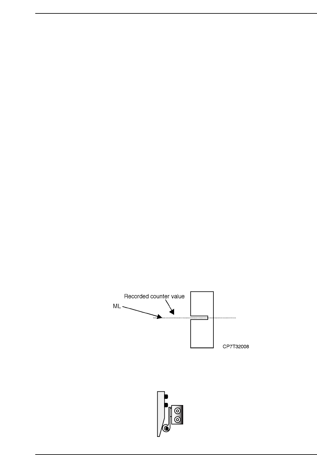
2.3.1 Middle Loading Position ML
Procedure:
1. Take the lower value of ZL_IN and ZL_OUT and deduct 9250 pulses
(18.5 mm). (CP-742E(ME): 14000 pulses (28 mm))
e.g. CP-732E
ZL_IN = 15750
ZL_OUT = 15725
Middle Loading Position ML = 15725 - 9250
= 6475 pulses
Record this motor pulse count.
e.g. CP-742E(ME)
ZL_IN = 23300
ZL_OUT = 23275
Middle Loading Position ML = 23275 - 14000
= 9275 pulses
Record this motor pulse count.
2. Move the Z-axis to that position (ML), then move the X-axis from
XL_OUT to XL_IN by hand, verifying that there is no interference
between the OUT-carrier cylinder/nut and the table piping.
2.3.2 Upper Limit Sensor 1
1. The upper limit sensor dog should be adjusted to trigger when the Z-axis
is at ML-125 ± 50 pulses.
2. Confirm the position of the dog using the I/O, [MAINTENANCE] - [I/O
CHECK] - [STANDARD] - [X05C Table Loading Height Check].
2.3.3 Rail Clamper Adjustment
1. Adjust the rail clamper air valve to activate the clamper at ZL(lower) -
650 ± 50 pulses.
Loosen and adjust up or down
CP7T32009
Chapter 2 2.3 Z-Axis Calibration Data Adjustments
Edition 2.0 2-9 CP-7-series Level 3 Tutorial
2.3.4 ZØ Measurement
1. Activate the station 9 solenoid valve with the cam at 0°.
[MAINTENANCE] → [I/O CHECK] → [STANDARD] → [Y034 PLACE
SOL ENGAGED].
2. Mount the CP-7-series ZØ adjustment jig on the center of the main
clamper. Attach the nozzle jig to Head A no. 1. Then inch the XY-table
to the placing position at station 9.
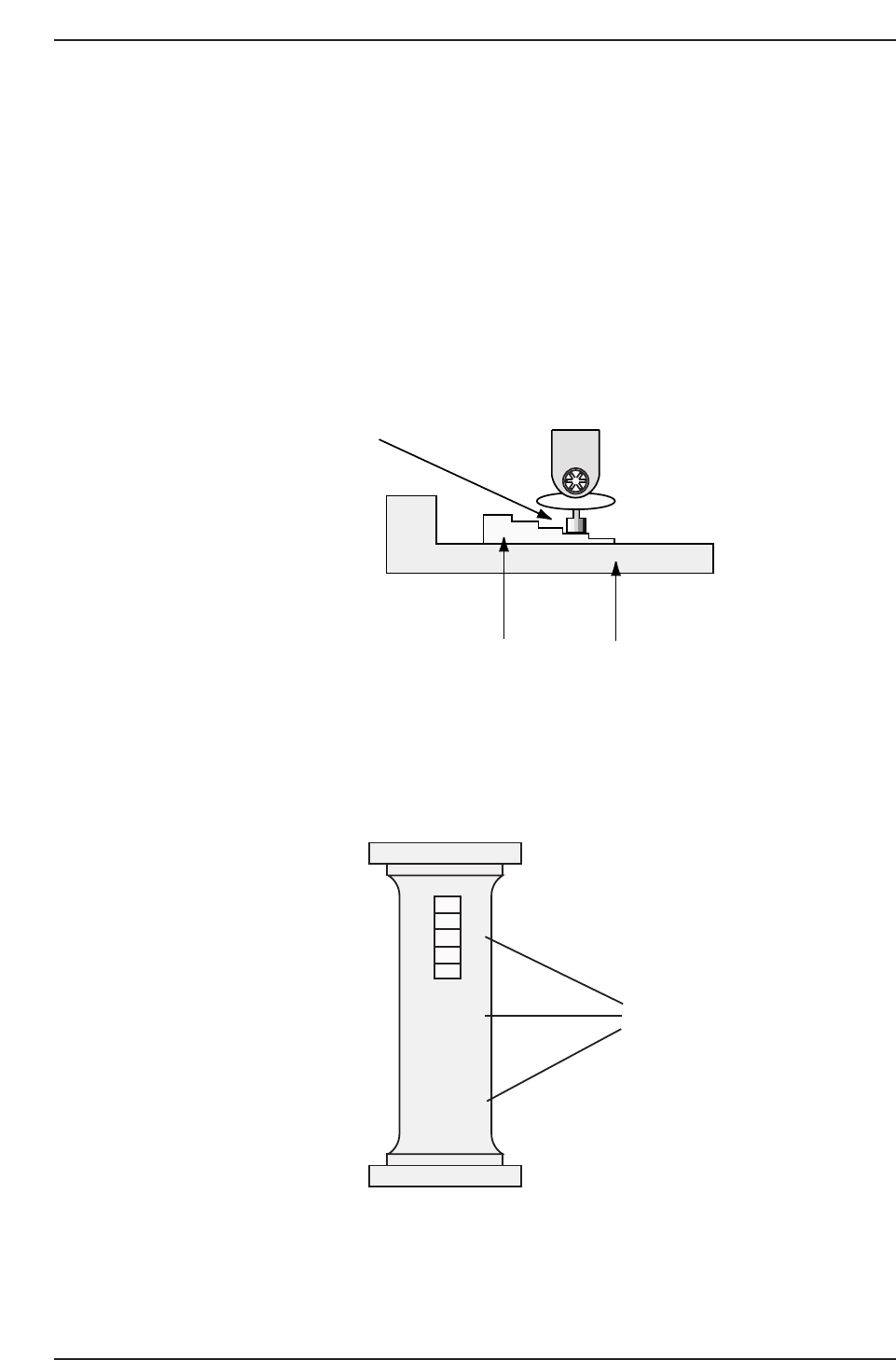
3. With the cam angle at 180°, raise the Z-axis until the nozzle jig just comes
into contact with the -0.3 mm spacer. Record the motor pulse count.
4. Repeat the adjustment with the spacer at the middle and at the front of
the bar jig as shown below. Take the average of the three values and
register the position in machine calibration data using the following
commands:
[MAINTENANCE] → [CALIBRATION] → [PLACING REF] → [SET].
Note: If no jig is available, use a fiducial plate jig and add 1000 pulses to the resultant value.
0
-0.1
-0.2
-0.3
-0.4
X
X
X
Measure at these
three points
CP7T32011
CP7T32010
0.3 mm
Nozzle jig (Z9326DCPJ4130)
Z adjustment jig (Z9530PJ1060/Z5313WPJ0180)
Chapter 2 2.3 Z-Axis Calibration Data Adjustments
Edition 2.0 2-10 CP-7-series Level 3 Tutorial

2.3.5 Middle OT Sensor
1. The middle OT sensor dog should be adjusted to trigger the sensor when
the Z-axis is at ZØ + 250 ± 50 pulses.
2. Confirm the position of the dog using the following commands:
[MAINTENANCE] → [I/O CHECK] → [STANDARD] → [X05E MAIN-
LIFTER MIDDLE OT].
Chapter 2 2.3 Z-Axis Calibration Data Adjustments
Edition 2.0 2-11 CP-7-series Level 3 Tutorial