CP7 Series Level3 Tutorial Manual.pdf - 第136页
8.2.4.2 Adjusting the Narrow Camera Procedure: 1. Install the cam lever stopper jig as shown in the diagram below before the clutch descends. This will prevent the clutch descending during measurement. 2. Insert a By-pas…
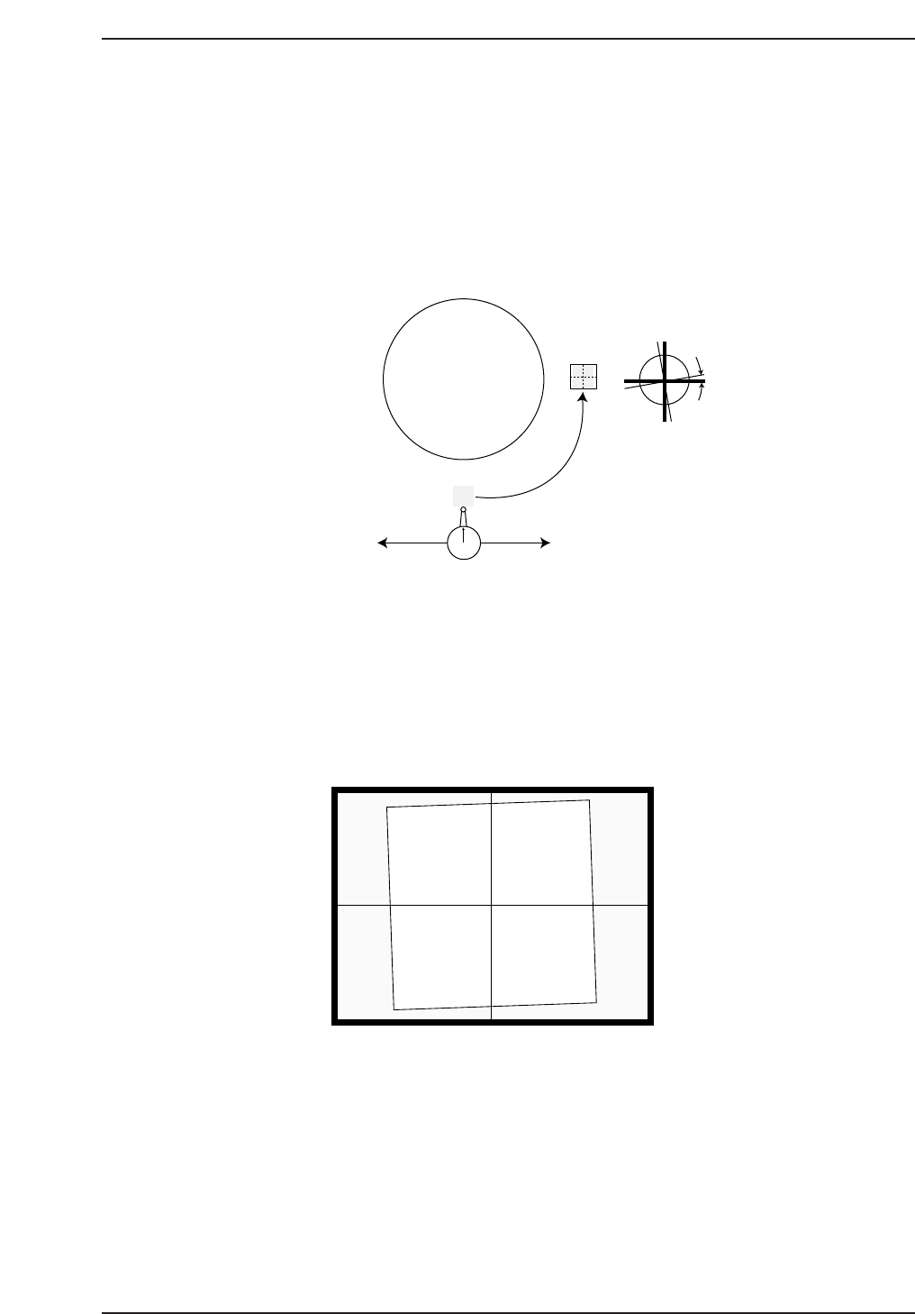
6. Inch the dial in the X-axis (1% inching speed) from right to left. Align
the nozzle jig parallel with the X-axis (within 0.01 mm) by rotating the
nozzle shaft.
7. Remove the dial gauge and inch the cam in the clockwise direction to 0°.
Position the shaft at 200°, station 5 using the following commands:
[MAINTENANCE] → [CALIBRATION] → [PARTS CAMERA
RESOLUTION] → [MOVE] → START.
8. Press [MEASURE] → START to perform the measurement procedure.
Confirm that the resolution and skew fall within the following ranges:
Delta (skew) Q: 0 ± 0.05 deg
Wide Camera (resolution) X : 43.17 ~ 47.72 um/pixel
Wide Camera (resolution) Y : 43.40 ~ 47.96 um/pixel
9. If the resolution is out of range, loosen the lens cover, and adjust the
camera height. Return the lens cover to its original height 0.5 mm above
the prism box.
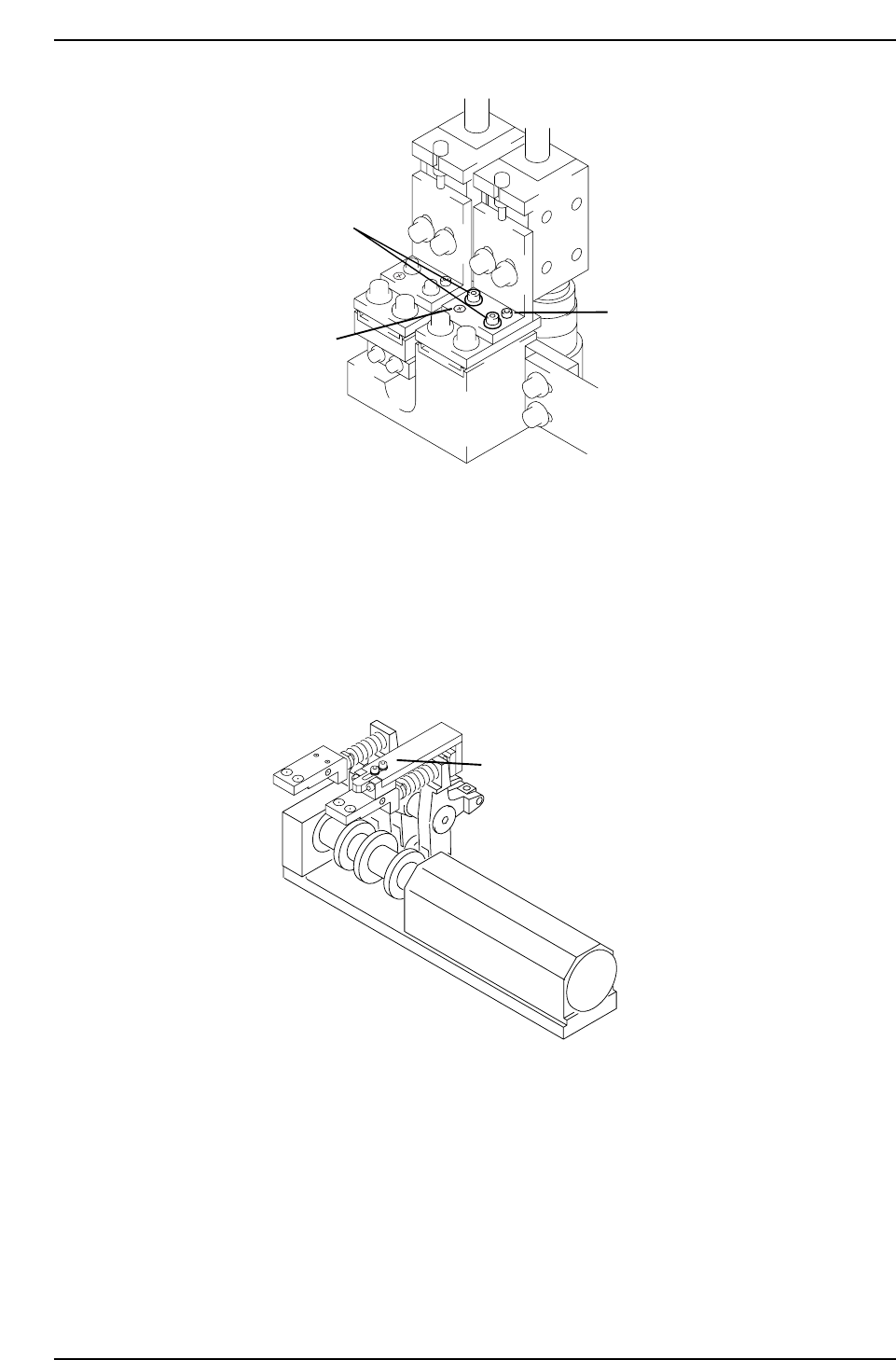
10. To adjust Delta Q, loosen the two (2) fixing bolts holding the camera
position and turn the adjustment bolt to alter the camera angle. Repeat
until within range. Tighten fixing bolts when finished and recheck
(torque = 8 Nm).
Camera Monitor
CP7T38013
Turret
Delta Q
5th Station
9th Station
CP7T38012
Chapter 8 8.2 Parts Camera Adjustments
Edition 2.0 8-9 CP-7-series Level 3 Tutorial
8.2.4.2 Adjusting the Narrow Camera
Procedure:
1. Install the cam lever stopper jig as shown in the diagram below before
the clutch descends. This will prevent the clutch descending during
measurement.
2. Insert a By-pass key into both front door interlocks.
3. Atach the narrow camera nozzle jig on Head A No.1, at station 9.
4. Remove the back-up pin plates and attach the XY-table magnet stand to
the XY-table.
5. Rotate the shaft with the jig attached to 200° station 9 with the pick-up
solenoid off. Set the dial gauge to the stand and attach the needle to the
horizontal flat edge of the jig.
Station 8
Attach jig here
CP7T38015
Fixing bolts
Adjustment
bolt
Pivot
CP7T38014
Chapter 8 8.2 Parts Camera Adjustments
Edition 2.0 8-10 CP-7-series Level 3 Tutorial
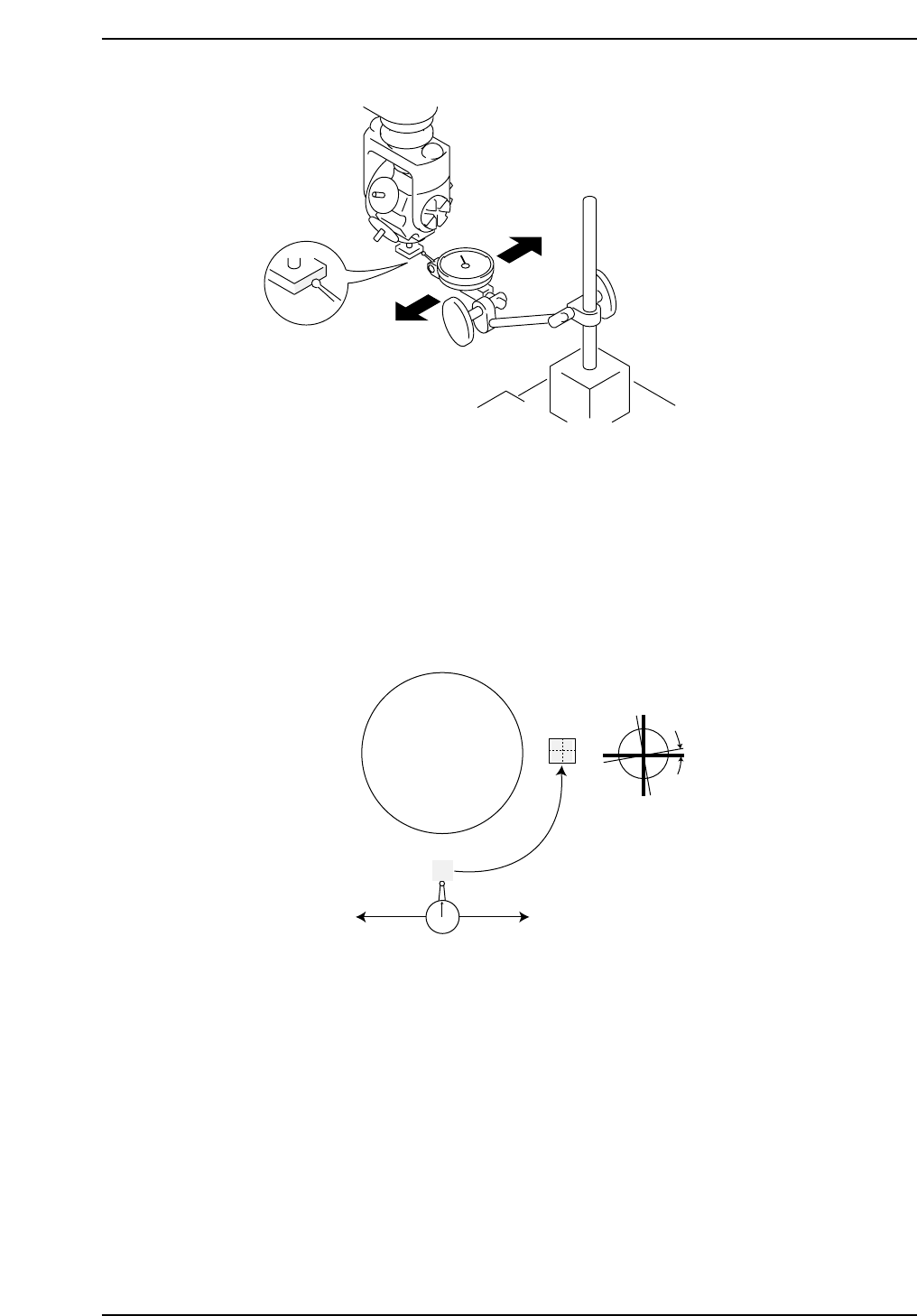
6. Inch the dial in the X-axis (1% inching speed) from right to left. Align
the nozzle jig parallel with the X-axis (within 0.01 mm) by rotating the
nozzle shaft.
7. Remove the dial gauge and inch the cam in the clockwise direction to 0°.
Position the shaft at 200°, station 5 using the following commands:
[MAINTENANCE] → [CALIBRATION] → [PARTS CAMERA
RESOLUTION] → [MOVE] → START.
8. Press [MEASURE] → START to perform the measurement procedure.
Confirm that the resolution and skew fall withing the following ranges:
Delta (skew) Q: 0 ± 0.05 deg
Narrow Camera (resolution) X : 11.81 ~ 13.06 um/pixel
Narrow Camera (resolution) Y : 11.88 ~ 13.13 um/pixel
9. If the resolution is out of range, loosen the lens cover, and adjust the
camera height. Return the lens cover to its original height 0.5 mm above
the prism box.
Turret
Delta Q
5th Station
9th Station
CP7T38017
CP7T38016
Chapter 8 8.2 Parts Camera Adjustments
Edition 2.0 8-11 CP-7-series Level 3 Tutorial