CP7 Series Level3 Tutorial Manual.pdf - 第58页
Affected Calibration Data: Placing Position X → MC0PPX Placing Position Y → MC0PPY Procedure: 1. Verify that the Station 9 solenoid valve is off. 2 . Remove the right hand side claw from the fixed side of the main convey…
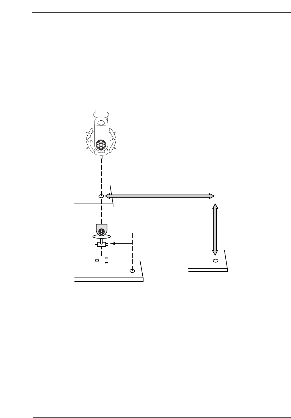
2.1 Placing Position (XØ, YØ)
Placing position X and Y positions correspond to the X and Y servo counter values
that are required to move the XY-table from the zero pulse position in the X and Y-
axes to the position where the program origin (-5,5) in the case of Fuji machines) is
aligned with the center of the nozzle on Head A at station 9. One pulse
corresponds to 0.002 mm.
If an incorrect value is input for XØ, YØ, component placement will be off by an
amount equal to the error (refer to the figure below).
Required Tools: None
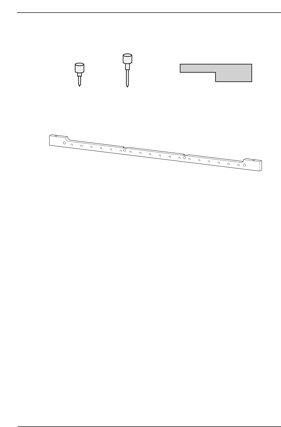
Required Jigs: Pin holder jig
Centering gauge
Centering jig
Dial holder
Dial gauge
Placing Position Y
Program
Coordinates
CP7T32001
11 St
Placing Position X
Chapter 2 2.1 Placing Position (XØ, YØ)
Edition 2.0 2-1 CP-7-series Level 3 Tutorial
Affected Calibration Data: Placing Position X → MC0PPX
Placing Position Y → MC0PPY
Procedure:
1. Verify that the Station 9 solenoid valve is off.
2. Remove the right hand side claw from the fixed side of the main
conveyor clamper.
3. Attach the pin holder jig to the XY-table. As the CP-732 does not support
the use of tooling pins, it is necessary to use this jig as a temporary
reference pin holder. From the front side, align the jig to the upper right
hand corner.
Note: In the case of either the CP-742E or the CP-742ME, which do support tooling pins,
simply remove the reference tooling pin and spring, and insert the jig in its place.
4 Use the inching keys to move the reference tooling pin insertion position
near station 9. Turn the servo power OFF.
5. Manually lower the Z-axis to the minus mechanical stopper position (-
1000 pulses) and insert the centering jig into the reference pin insert
position.
6. Remove the nozzle holder from shafts P, A, and B and install the dial
holder and dial gauge to holder A as shown opposite.
Centering jig
Dial holder (GPJ1030)
Pin holder jig Z9426DCPJ4451
CP7T32002
DGPJ0030DCPJ0250
CP-732E
CP-742E(ME)
CP-732E Only
Chapter 2 2.1 Placing Position (XØ, YØ)
Edition 2.0 2-2 CP-7-series Level 3 Tutorial
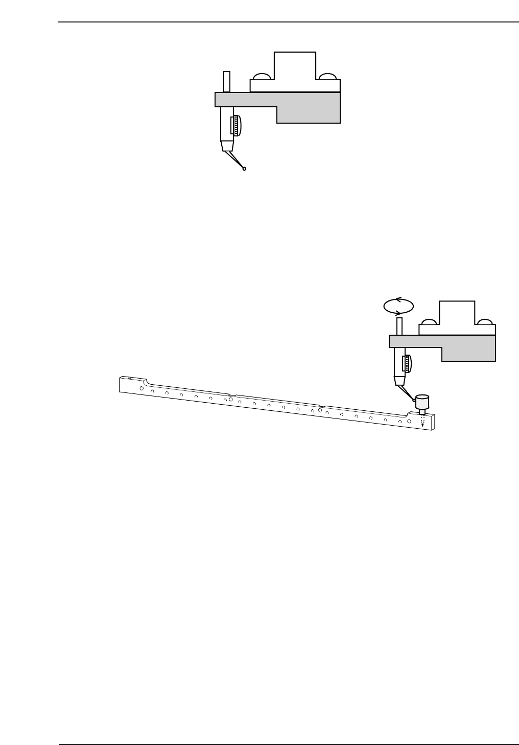
7. With the cam at 180°, move the XY-table until the centering jig is directly
below Station 9. Position the needle of the dial gauge against the side
surface of the centering jig and set to zero.
8. While rotating the dial gauge around the centering jig, manually move
the XY-table in the X and Y-direction until the dial reads zero on all
sides. Tolerance = 0 ± 0.01 mm. This position is XØ, YØ.
9. Register the motor pulse counts of the X and Y-axes at this point in
calibration data using the following commands:
[MAINTENANCE] → [CALIBRATION] → [PLACING REFERENCE] →
[SET] (XØ, YØ).
CP7T32004
Shaft A
CP7T32003
Chapter 2 2.1 Placing Position (XØ, YØ)
Edition 2.0 2-3 CP-7-series Level 3 Tutorial