CP7 Series Level3 Tutorial Manual.pdf - 第84页
3.3 D-Axis Pallet Adjustments 3.3.1 Pallet Upper/Lower End Sensor Adjustments Procedure: 1. Inch the axis to the counter zero position (10 mm from the stopper). 2. Move the pallet to the upward end by manually operating …

Notes:
Chapter 3 3.2 D-Axis Adjustments
Edition 2.0 3-12 CP-7-series Level 3 Tutorial
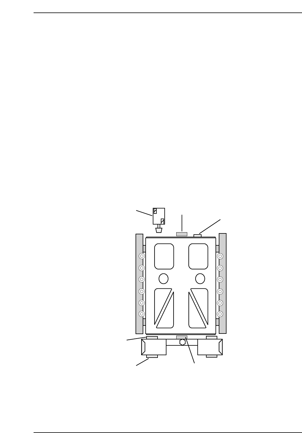
3.3 D-Axis Pallet Adjustments
3.3.1 Pallet Upper/Lower End Sensor Adjustments
Procedure:
1. Inch the axis to the counter zero position (10 mm from the stopper).
2. Move the pallet to the upward end by manually operating the pallet
upward solenoid valve.
3. Insert the Pallet Change Unit (PCU) and lock in position. Move the
pallet to the PCU. Remove the PCU.
4. Place a 0.5 mm feeler gauge on the four pallet clamp surfaces.
5. Slide the pallet back into position and ensure that it contacts the stopper
(2).
6. Lower the pallet with a 0.5 mm feeler gauge between the jig and the four
clamp surfaces. Adjust the sensor position so that the pallet lower end
sensor (3) turns OFF at this position and activates when the 0.5 mm
feeler gauges are removed
7. Next adjust the upward end sensor (4) so that the sensor turns OFF when
lowered 0.5 mm from the upward end.
7
(3, 4)
2
5
6
3
CP7T33015
Chapter 3 3.3 D-Axis Pallet Adjustments
Edition 2.0 3-13 CP-7-series Level 3 Tutorial

3.3.2 Table Interlock Sensor
Procedure:
1. Place a 1 mm feeler gauge between the stopper and the jig in order to
adjust the pallet interlock sensor (5). Adjust both interlock sensor
amplifier volumes to 1/4 from the MIN. When the feeler gauge is
inserted, the sensor should turn off. When the feeler gauge is removed,
the sensor should activate.
3.3.3 Pallet Stopper
Procedure:
1. To adjust the pallet stopper (7), inch the D-axis to zero pulses, and
manually extend the stopper to contact the table using the solenoid
valve.
2. Loosen the stopper bracket and move from left to right to find the
middle of the play. Secure the bracket in this position.
3. Loosen the sensor with a small screwdriver and tighten at position 0.5
mm from where the sensor activates.
4. The speed controller should be set 3 rotations from the fully closed
position.
3.3.4 Pallet Air Cylinder Sensor
Procedure:
1. Ensure that the pallet is in the downward position.
2. Inch the pallet from the zero counter position until the air cylinder
becomes visible.
3. Set the retract end sensor at 0.5 mm from the ON position. The
downward speed controller should be set 5 revolutions from fully
closed.
4. Manually raise the pallet to the upward position and set the advance end
sensor at 0.5 mm from the ON position. The upward speed controller
should be set 4.5 revolutions from fully closed.
Speed Controller
CP7T33013
Chapter 3 3.3 D-Axis Pallet Adjustments
Edition 2.0 3-14 CP-7-series Level 3 Tutorial