CP7 Series Level3 Tutorial Manual.pdf - 第61页
2.2 Loading Position Adjustments Perform the XL, YL, ZL, ML measurements as described below. Affected Calibration Data: Loading Pos. YL-IN → MC0PCPY Loading Pos. YL_OUT → MC0PRPY Loading Pos. XL_IN → MC0PCPX Loading Pos.…

Notes:
Chapter 2 2.1 Placing Position (XØ, YØ)
Edition 2.0 2-4 CP-7-series Level 3 Tutorial
2.2 Loading Position Adjustments
Perform the XL, YL, ZL, ML measurements as described below.
Affected Calibration Data: Loading Pos. YL-IN → MC0PCPY
Loading Pos. YL_OUT → MC0PRPY
Loading Pos. XL_IN → MC0PCPX
Loading Pos. XL_OUT → MC0PCPX
Loading Pos. ZL_IN → MC0PCPZ
Loading Pos. ZL_OUT → MC0PRPZ
Loading Pos. ML → MC0EPZ
ZØ Origin Pos. → MC0PPZ
2.2.1 Measuring YL_IN, YL_OUT
Procedure:
1. Remove the fixed-rail board stoppers from the IN and OUT-loaders.
2. Move the Y-axis to the 0 pulse position, and the X-axis to the -11250
pulse position.
3. Use an I/O command to open the main clamp. [MAINTENANCE] →
[I/O CHECK] → [STANDARD] → [Y044 XY-Table Panel Unclamp].
5. Raise the Z-axis to the point where the fixed rail of the conveyor and the
and the main table claws align in the Z-direction (approximately 16000
(CP-742E(ME): 23100)). Attach a dial gauge to the carrier bracket and
zero against the edge of the IN/OUT conveyor fixed rail.
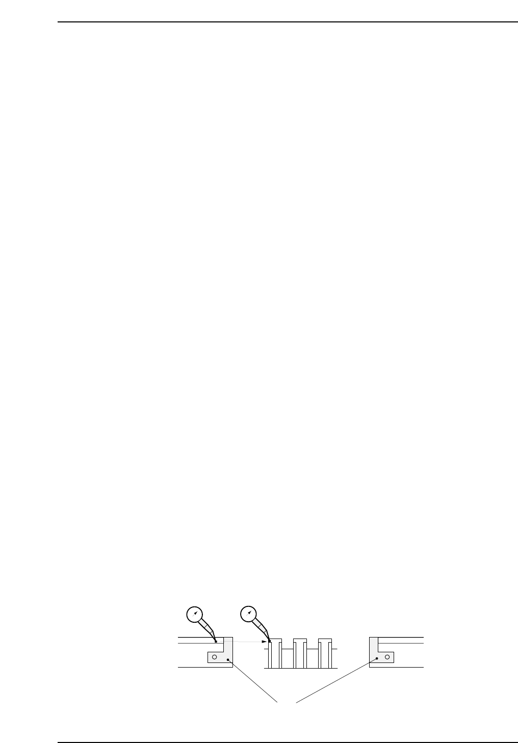
6. Manually move the carrier until the dial gauge contacts the horizontal
surface on the main table clamper as shown below.
7. Inch the Y-axis until the dial gauge registers zero. Repeat for YL_IN
with the X-axis at -220500 (CP-742E(ME): -271000).
8. Record YL loading position values in calibration data using the
following commands:
[MAINTENANCE] → [CALIBRATION] → [LOADING POS]
IN OUT
CP7T32005
0
First remove board stoppers
Main Table
Align the conveyor with
the main table
0
Chapter 2 2.2 Loading Position Adjustments
Edition 2.0 2-5 CP-7-series Level 3 Tutorial
2.2.2 Measuring XL_IN, XL_OUT
Procedure:
1. Move the OUT-carrier to the advance limit positions.
2. Manually inch the XY-table to YL_OUT in the Y direction and to the -
11250 pulse position in the X direction.
3. Press the EMERGENCY STOP button, then ensuring that both the main
conveyor clamper and the OUT carrier clamper are both closed, raise the
Z-axis to approximately 15000 pulses (CP-742E(ME): 23100). At this
point, the clamper claws and the carrier claws should be engaged. If not,
raise the Z-axis accordingly.
4. Using the motor coupling, manually move the X-axis carefully until the
carrier claws on the front carrier are perfectly aligned with the claws on
the reference clamper. Record the motor pulse count.
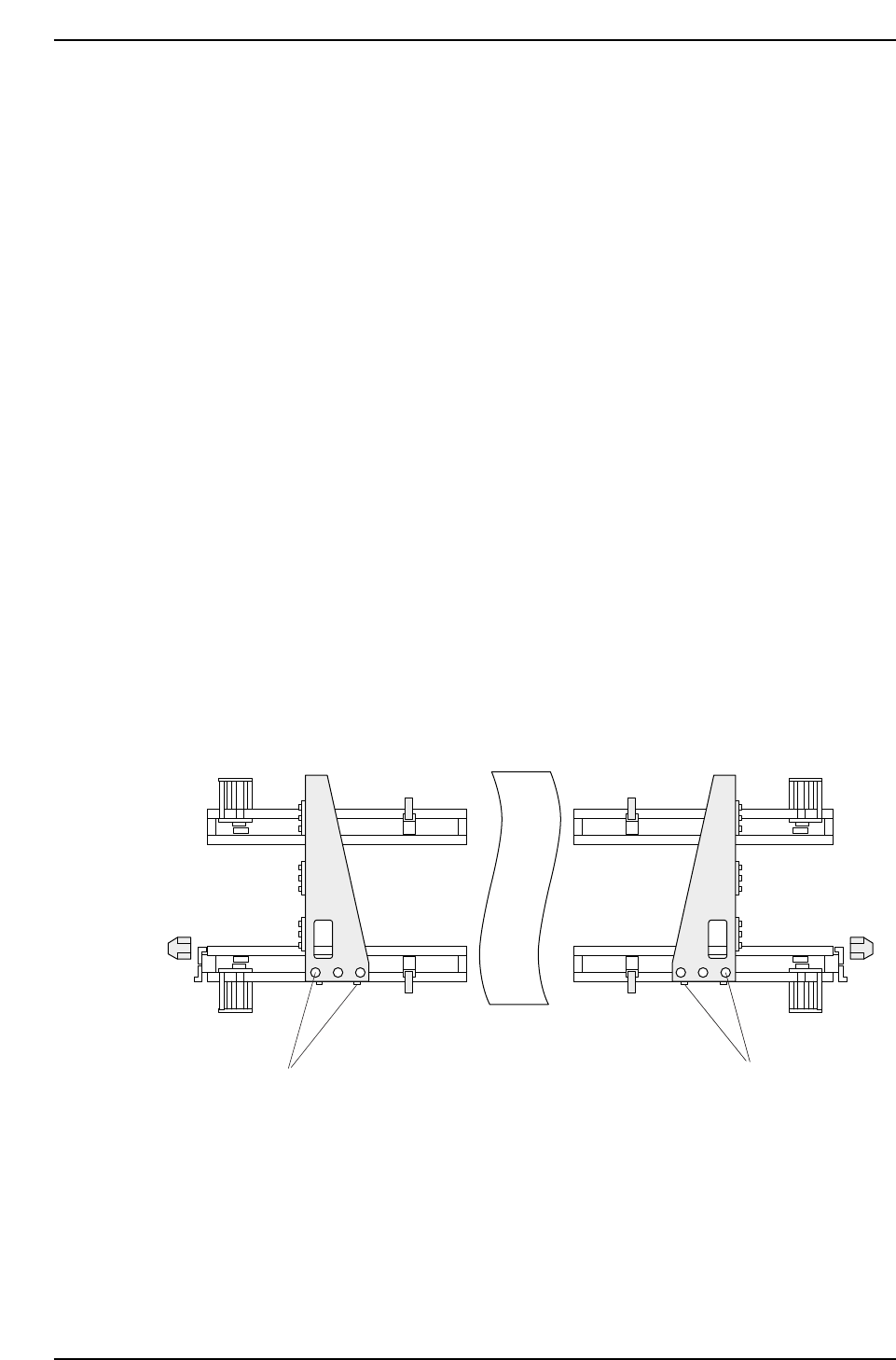
5. To align the claws on the rear side, loosen all five (5) bolts on the carrier
bracket (see figure below) and slide the bracket from left to right until in
position. Finally, tighten the bolts carefully.
6. Repeat the process for XL_IN, moving the Y-axis to YL_IN and the X-axis
to the - 220500 pulse position (CP-742E(ME): -271000).
7. Record XL loading position values in calibration data using the
following commands:
[MAINTENANCE] → [CALIBRATION] → [LOADING POS]
Adjustment bolts(5)
Adjustment bolts(5)
CP7T32006
Chapter 2 2.2 Loading Position Adjustments
Edition 2.0 2-6 CP-7-series Level 3 Tutorial