CP7 Series Level3 Tutorial Manual.pdf - 第94页
Q-Axis Timing Belt T ension V alues 4 . Tighten the two (2) positioning bolts and reconnect the electrical connections. Notice Note that as the CP-7 utilizes absolute encoders on all axes, it is no longer necessary to bo…
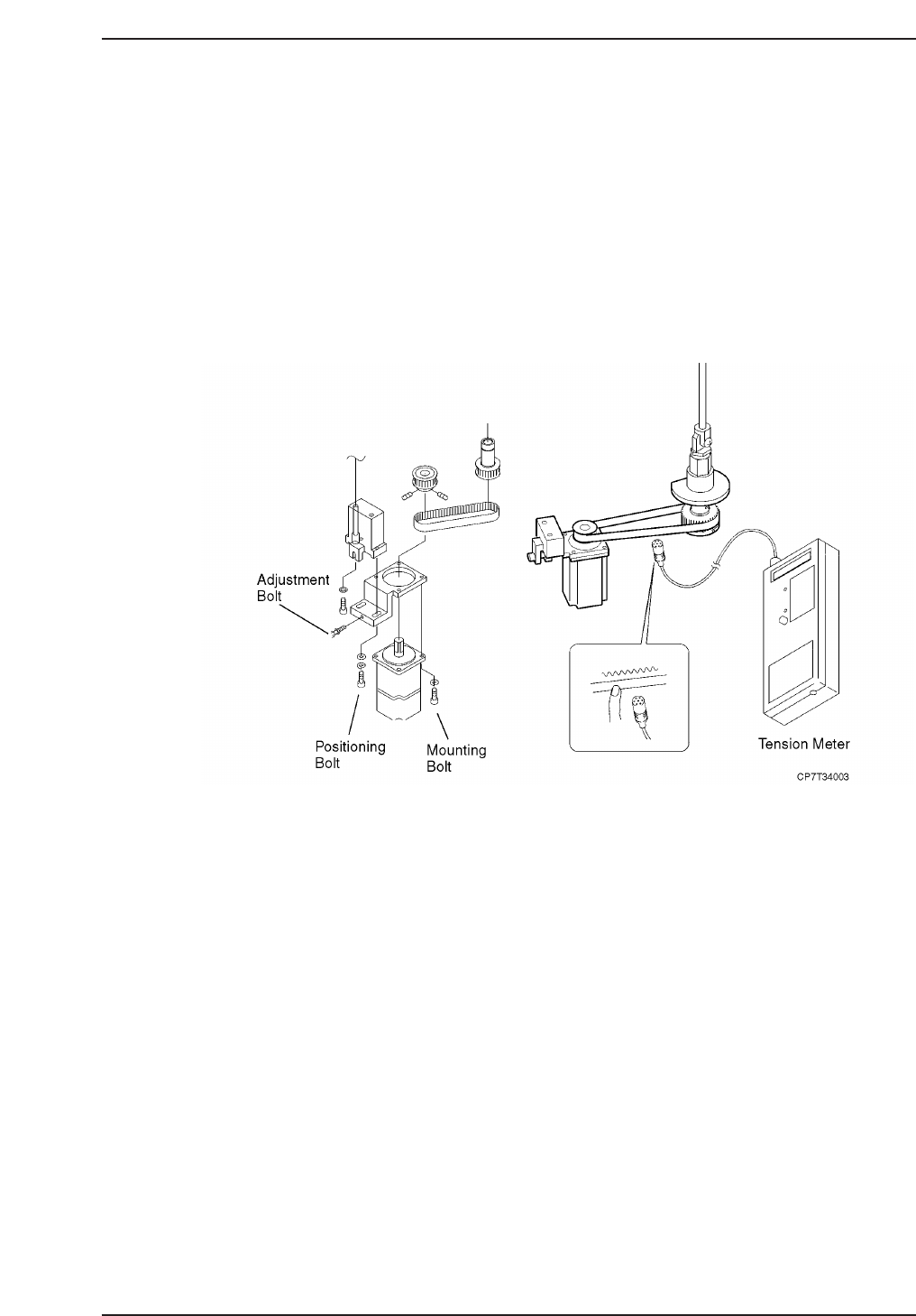
4.1.1 Removing the Q-Axis Motor
Procedure:
1. Turn OFF the machine power.
2. Disconnect both electrical connections to the motor.
3. Loosen the two (2) bolts on the underside of the timing belt adjustment
bracket, then adjust the jack bolt to lower the timing belt tension.
4. Remove the timing belt.
5. Separate the gear from the motor by loosening the set screw and remove.
6. Remove the four (4) positioning bolts fixing the motor to the mounting
bracket and then remove the motor.
4.1.2 Installing the Q-Axis Motor
Procedure:
1. Replace the motor and secure in place using the four (4) positioning
bolts.
2. Replace the motor gear and secure by tightening the set screw.
3. Replace the timing belt and adjust the tension as shown above according
to the table on the following page.
Chapter 4 4.1 Replacing the Q-Motors
Edition 2.0 4-3 CP-7-series Level 3 Tutorial
Q-Axis Timing Belt Tension Values
4. Tighten the two (2) positioning bolts and reconnect the electrical
connections.
Notice
Note that as the CP-7 utilizes absolute encoders on all axes, it is no
longer necessary to boot up the machine in Mechacheck mode when
performing motor adjustments.
N001
Axis
Tension
PQ
FQ
RQ
220 ± 5 Hz
242 ± 5
214 ± 5 Hz
Hz
CP7T34004
Chapter 4 4.1 Replacing the Q-Motors
Edition 2.0 4-4 CP-7-series Level 3 Tutorial
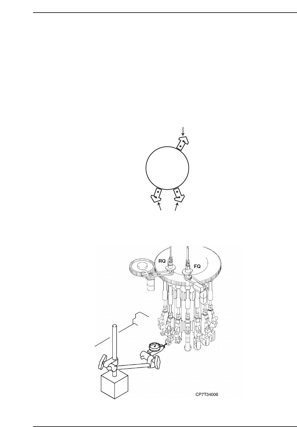
4.2 Q-Axis Adjustments
Procedure:
1. Rotate the cam axis to 200° and manually rotate the placing shaft until
the Q-axis motor pulse count is close to zero. Servo power on.
2. Remove the nozzle holder from the placing shaft at the Q-axis and also
the two (2) adjacent holders.
3. Slowly inch the Q-axis motor until the flat surface of the jig is as parallel
to the X-axis as possible. For each axis, use the surface of the jig shown
in the diagram below.
4. In the case of the the PQ-axis, attach dial gauge to device table one or in
the case of the FQ or RQ-axis, attach dial gauge to the XY-table.
2
8
10
Cam
Turret
CP7T34005
Chapter 4 4.2 Q-Axis Adjustments
Edition 2.0 4-5 CP-7-series Level 3 Tutorial