CP7 Series Level3 Tutorial Manual.pdf - 第80页
CP-732E Calibration Data Servo Count Chart (D1-axis) CP-732E Calibration Data Servo Count Chart (D2-axis) Caution Ensure that new Calibration data is backed-up to the host computer once the adjustment procedure is comple…
Alternative Method
Procedure:
1. Press the EMERGENCY STOP button to release the servo lock.
2. Mount an empty 8 mm tape feeder to the first position on the device
table to be calibrated.
3. Clear the EMERGENCY STOP, and inch device pallet 1 (2) to the pick-up
position at station 1.
4. Move Head A to Station 1 and select a 1.3 or 1.8 mm nozzle.
5. Move the device pallet by hand so that the tape feeder lies immediately
below the nozzle at Station 1.
6. Activate the pick-up solenoid using the following commands:
[MAINTENANCE] → [I/O CHECK] → [STANDARD] → [Y031 PICKUP
SOLENOID ENGAGED].
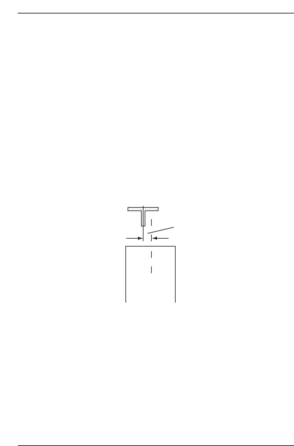
7. Rotate the cam angle to 180° and confirm that the nozzle is directly
above the center of the tape cavity.
8. If not properly aligned, manually rotate the ballscrew until the nozzle is
postioned directly above the center of the cavity.
9. Register this position in machine calibration data using the following
command:
[MAINTENANCE] → [CALIBRATION] → [PICK-UP REFERENCE] →
[SET].
10. Repeat the process for T2.
Should be no space
CP7T33008
Chapter 3 3.2 D-Axis Adjustments
Edition 2.0 3-8 CP-7-series Level 3 Tutorial
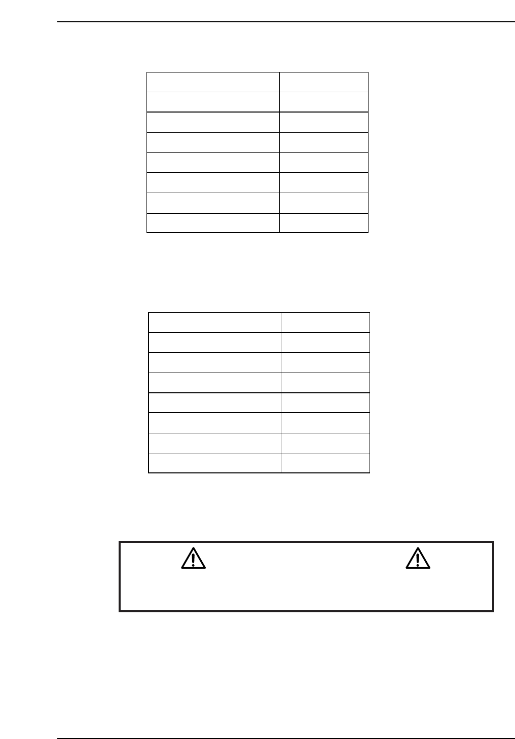
CP-732E Calibration Data Servo Count Chart (D1-axis)
CP-732E Calibration Data Servo Count Chart (D2-axis)
Caution
Ensure that new Calibration data is backed-up to the host computer
once the adjustment procedure is complete.
CN002
CP7T33010
Minus mechanical stopper
- OT sensor ON
Max limit pos.D2
D2 Origin
Pickup pos. T2
+ OT sensor ON
Plus mechanical stopper
-5000 ± 50
-1500 ± 50
-1000 ± 50
0 ± 1000
264300
Min limit pos. D2 507000 ± 1000
508500 ± 1000
507500 ± 1000
Plus mechanical stopper
-OT sensor ON
Max limit pos.D1
D1 Origin
Pickup pos. T1
+OT sensor ON
Minus mechanical stopper
5000 ± 50
1500 ± 50
1000 ± 50
0 ± 1000
-504700
Min limit pos. D1 -507000 ± 1000
-508500 ± 1000
-507500 ± 1000
CP7T33009
Chapter 3 3.2 D-Axis Adjustments
Edition 2.0 3-9 CP-7-series Level 3 Tutorial
Chapter 3 3.2 D-Axis Adjustments
Edition 2.0 3-10 CP-7-series Level 3 Tutorial
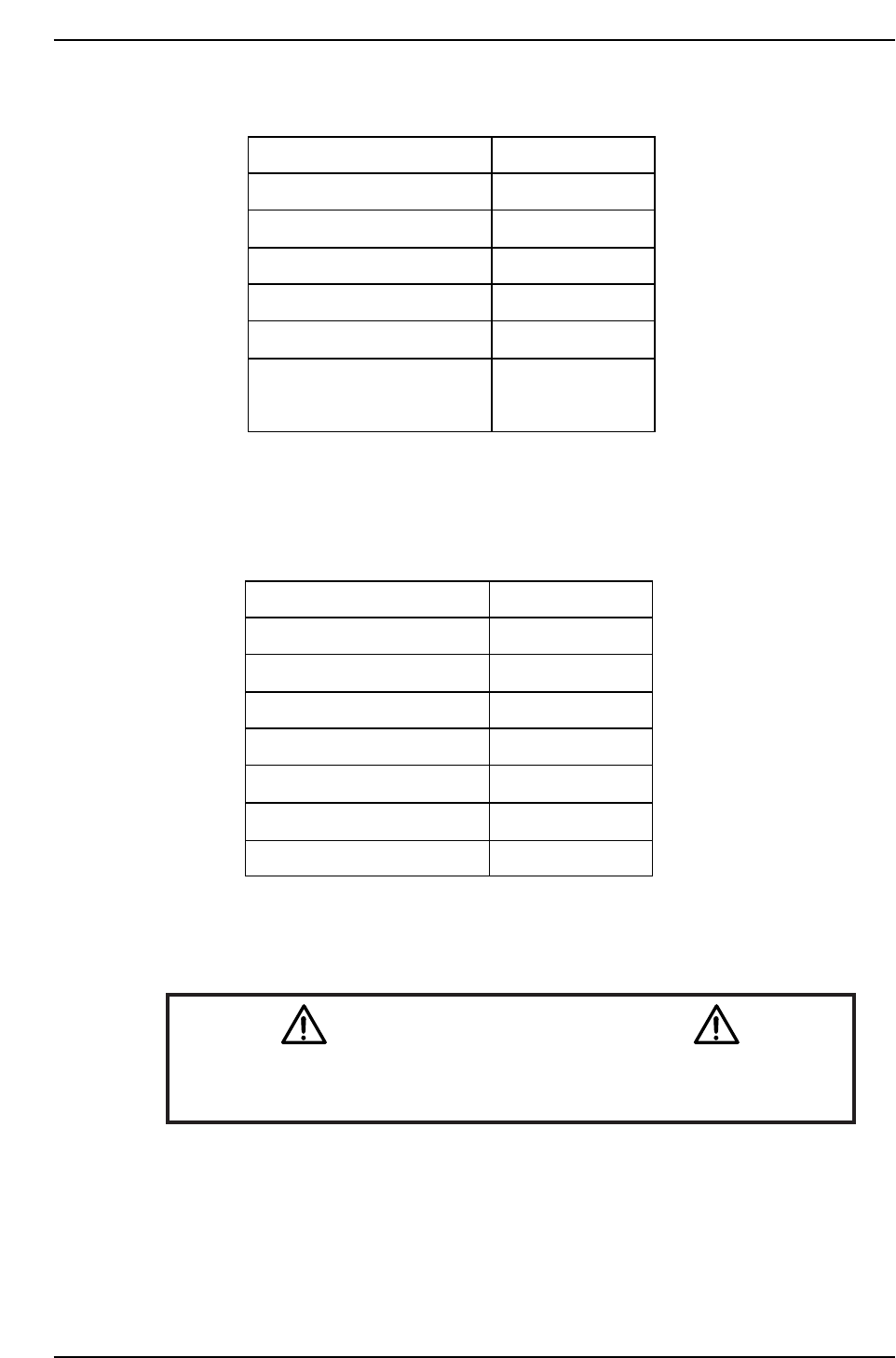
CP-742E Calibration Data Servo Count Chart (D1-axis)
CP-742E Calibration Data Servo Count Chart (D2-axis)
Caution
Ensure that new Calibration data is backed-up to the host computer
once the adjustment procedure is complete.
CN002
CP7T33012
Minus mechanical stopper
-OT sensor ON
Max limit pos.D2
D2 Origin
Pickup pos. T2
+OT sensor ON
Plus mechanical stopper
-5000 ± 50
-1500 ± 50
-1000 ± 50
0 ± 1000
591300
Min limit pos. D2 1153500 ± 1000
1157500 ± 1000
1154000± 1000
CP7T33011
Plus mechanical stopper
-OT sensor ON
Max limit pos.D1
D1 Origin
Pickup pos. T1
+OT sensor ON
Minus mechanical stopper
5000 ± 50
1500 ± 50
1000 ± 50
0 ± 1000
-1150700
Min limit pos. D1
-1153500 ± 1000
-1157500 ± 1000
-1154000 ± 1000