CP7 Series Level3 Tutorial Manual.pdf - 第12页
Safety Guidelines Fuji machines are designed and pr oduced with safety as one of our main considerations. However , even a perfectly designed machine can be damaged, or someone can still be injured if the user does not f…

Chapter 9 Placing Accuracy Measurement
9.1 PAM....................................................................(Edition 2.0)..........9-1
9.1.1 Overview.........................................................................................................9-1
9.1.2 Getting Started................................................................................................9-1
9.1.3 Operating the PAM Functions.........................................................................9-2
9.1.3.1 Entering and Exiting PAM Mode.............................................................9-2
9.1.3.2 Placing the PAM Parts............................................................................9-2
9.1.3.3 Measuring the Accuracy of Placement ...................................................9-3
9.1.3.4 Loading and Unloading Panels...............................................................9-3
9.1.3.5 Carrying Out PAM at the Machine..........................................................9-3
9.1.4 Measuring the PAM Placement ......................................................................9-4
9.1.4.1 Move Mode.............................................................................................9-4
9.1.4.2 Result......................................................................................................9-4
9.1.4.3 Indicate Distribution ................................................................................9-4
9.1.4.4 File Save.................................................................................................9-4
9.1.4.5 Renewal..................................................................................................9-4
9.1.4.6 Editing Offset Tolerance .........................................................................9-4
9.1.5 Displaying the Measurement Results .............................................................9-5
9.1.5.1 Change Nozzle .......................................................................................9-5
9.1.5.2 Edit USL/LSL ..........................................................................................9-5
9.1.5.3 Show Deviation.......................................................................................9-5
9.1.6 Editing USL and LSL.......................................................................................9-6
9.1.6.1 Set ..........................................................................................................9-6
9.1.6.2 Cp and Cpk Calculation Functions .........................................................9-6
9.1.7 Diplaying the Distribution................................................................................9-7
9.1.7.1 Changeover of Data Display...................................................................9-7
9.1.7.2 Changeover of Nozzle Display ...............................................................9-7
9.1.7.3 Changeover of Head Display..................................................................9-7
9.1.8 Updating the Machine Data ............................................................................9-8
9.1.8.1 Changeover of Nozzle Display ...............................................................9-8
9.1.8.2 Update Proper ........................................................................................9-8
9.1.8.3 1/1...........................................................................................................9-8
9.1.8.4 1/2...........................................................................................................9-8
9.1.8.5 Machine Data Format .............................................................................9-9
9.1.9 Editing the Offset Tolerances........................................................................9-10
9.1.9.1 Set ........................................................................................................9-10
9.1.9.2 Offset Tolerances .................................................................................9-10
9.1.10 Production Program Settings......................................................................9-11
9.1.11 Saved Files.................................................................................................9-12
Contents –
List of Current Pages
Edition 2.0 viii CP-7-series Level 3 Tutorial

Safety Guidelines
Fuji machines are designed and produced with safety as
one of our main considerations. However, even a
perfectly designed machine can be damaged, or someone
can still be injured if the user does not follow the safety
rules. It is the responsibility of the user to make sure all
safety rules are followed during operation and
maintenance.
Be sure to read these safety rules before operating the
machine. Keep this manual close to hand when
operating the machine.
Safety Guidelines
Edition 2.0 1 CP-7-series Level 3 Tutorial
1. About Symbols
To avoid injury to persons and damage to the machine, Fuji employs a number of messages
and symbols that are used in manuals and on the machines. Be sure you understand the
meanings of these symbols before reading the manual.
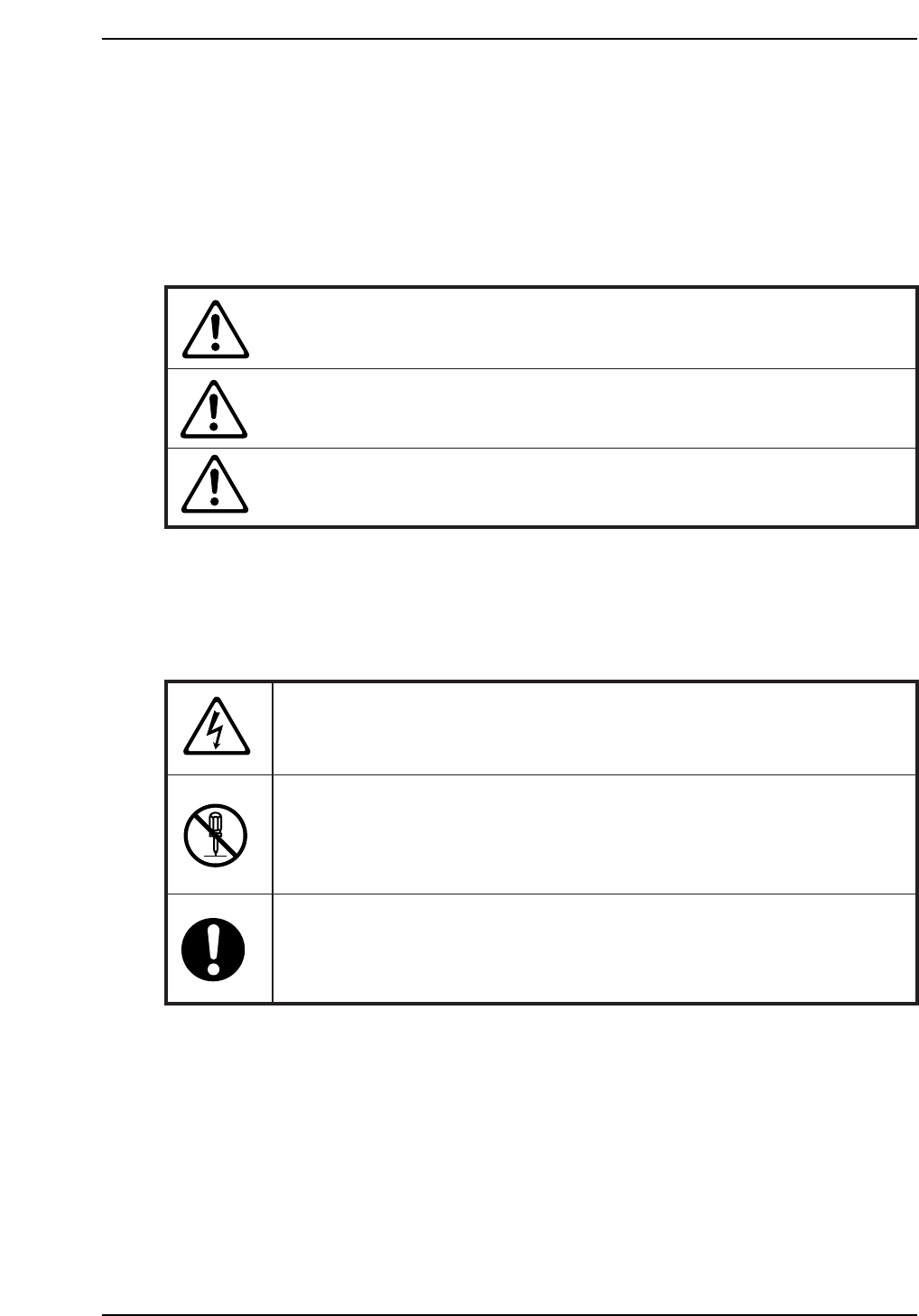
Hazard warnings are divided into the following three classes:
DANGER
The hazard or unsafe practice will cause severe injury or
death.
WARNING
The hazard or unsafe practice may cause severe injury or
death.
CAUTION
The hazard or unsafe practice may lead to personal injury
or damage to the machine.
To distinguish the type of hazard, the following symbols are used in combination with the
ones above.
Hazard Alert
A triangle is used to draw your attention to a hazard. The symbol inside the
triangle indicates the nature of the hazard (in this case electrical shock).
Prohibition
A circle with a diagonal line inside is used to draw your attention to an
operation that is prohibited. The symbol inside the circle indicates the nature
of the operation (in this case disassembly).
A circle with an exclamation mark is used to draw your attention to a
mandatory action. In other words, you are required to carefully carry out the
given instructions.