CP7 Series Level3 Tutorial Manual.pdf - 第43页
Chapter 1 1.5 Replacing the Z-Motor Edition 2.0 1-18 CP-7-series Level 3 T utorial Required Tools: 1 Set of Allen Wrenches 1 Torque Wrench 1 0.2 mm Filler Gauge 1 Dial Gauge 1 Tension Meter Required Jig: 1 Lock nut wrenc…
Chapter 1 1.5 Replacing the Z-Motor
Edition 2.0 1-17 CP-7-series Level 3 Tutorial
1.5 Replacing the Z-Motor
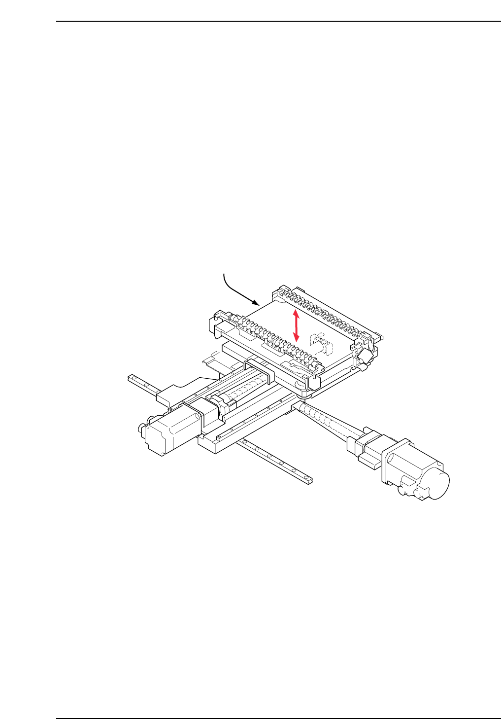
The Z-motor (refer to figure below) is responsible for moving the production table
down inside the machine in order to load and unload boards, and also to raise and
lower PCBs to the appropriate placing height based on the part height set in part
data.
A poorly adjusted or problematic Z-axis may prevent the PCB from being clamped
and unclamped properly when loading and unloading. It may also result in
damage to shafts or nozzles, or tombstoning of parts.
• Damage or slippage of the coupling that connects the Z-motor and the Z-axis ball
screw.
• After replacing the Z-motor
• After replacing the OT sensors, etc.
CP7T31015
Z-axis motor
Chapter 1 1.5 Replacing the Z-Motor
Edition 2.0 1-18 CP-7-series Level 3 Tutorial
Required Tools: 1 Set of Allen Wrenches
1 Torque Wrench
1 0.2 mm Filler Gauge
1 Dial Gauge
1 Tension Meter
Required Jig: 1 Lock nut wrench
Resolution: 0.002 mm/pulse World (Zero)
Affected Proper: Max Limit Z → MC0MAXZ
Min Limit Z → MC0MINZ
Caution
Ensure that a back-up of Proper data is taken prior to replacing the
motor.
CN001
DCPJ0700
CP7T31016
AWPJ8090
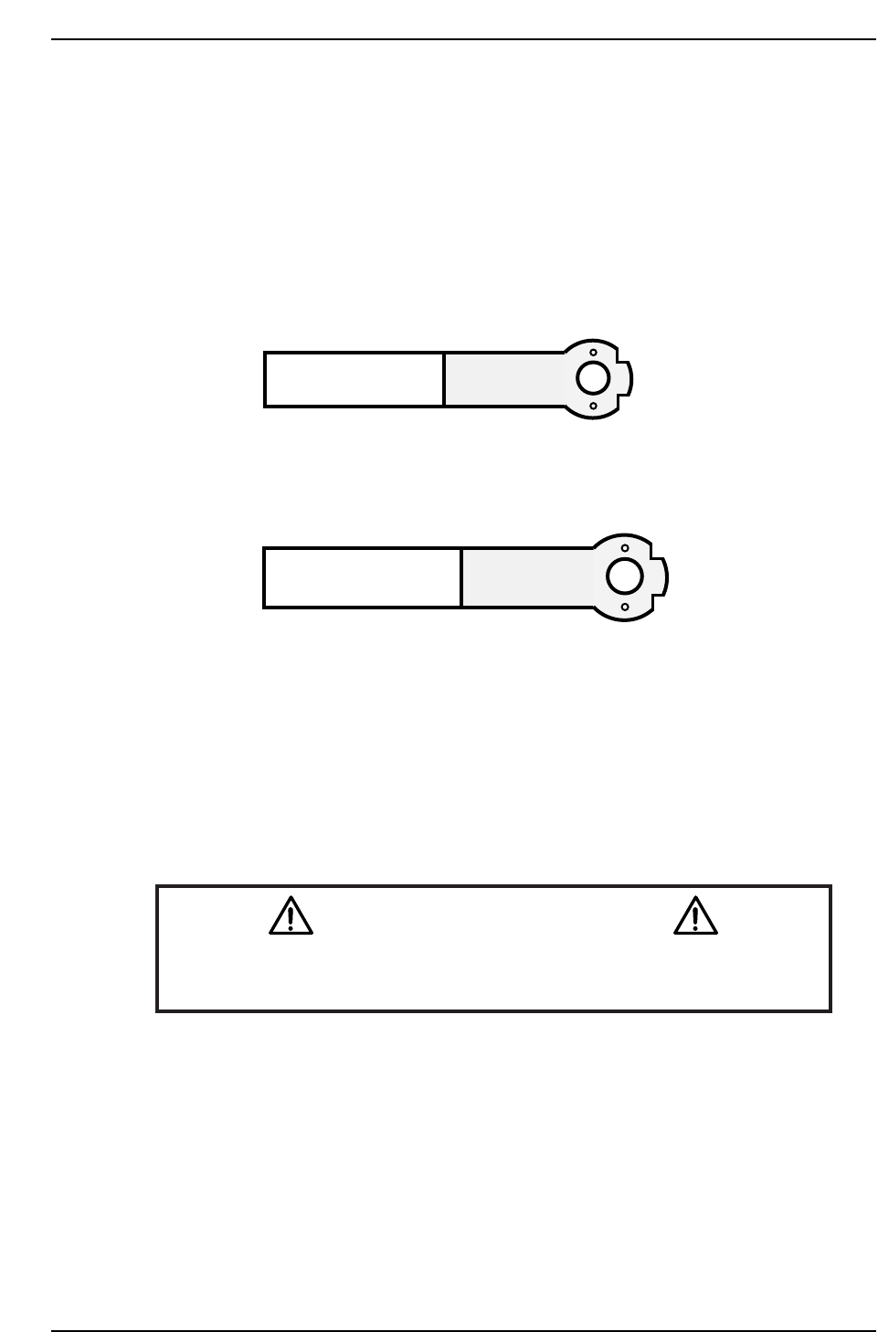
CP-732E
CP742E(ME)
Chapter 1 1.5 Replacing the Z-Motor
Edition 2.0 1-19 CP-7-series Level 3 Tutorial
1.5.1 Removing the Z-Axis Motor
Procedure:
1. Turn OFF the machine power.
2. Disconnect the two (2) electrical connections to the motor (at front of the
XY-table).
3. Retract both the IN and OUT carriers, and widen the machine’s conveyor
rails to allow better access to the machine.
4. Move the XY-table to the out loading position.
5. Manually raise the table using the Z-axis timing belt on the left hand side
of the table.
Note: It is possible that timing belt slippage may occur when adjusting the table height using
the timing belt at the right hand s ide o f the table..
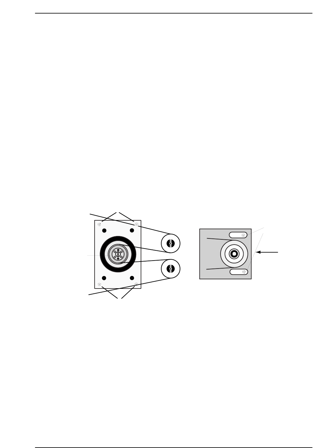
6. Loosen the belt tension by loosening the two (2) allen bolts on the right
hand side of the table, and then lower the tension using the adjustment
bolt as shown below.
8. Pop the span-ring by removing the four (4) allen bolts and screwing two
of them into the adjacent holes until loose. Remove the span-ring.
9. Remove the motor gear followed by the four (4) mounting bolts securing
the motor bracket to the XY-table.
10. Remove the motor and separate from the bracket by removing the four
(4) mounting bolts on the underside.
Tension
Adjustment
Bolt
Bracket Mounting
Bolts
Motor Mounting
Bolts
Z-motor
span-ring
CP7T31017
Loosen here