CP7 Series Level3 Tutorial Manual.pdf - 第41页
Chapter 1 1.4 Y -Axis Adjustments Edition 2.0 1-16 CP-7-series Level 3 T utorial Notes:
Chapter 1 1.4 Y-Axis Adjustments
Edition 2.0 1-15 CP-7-series Level 3 Tutorial
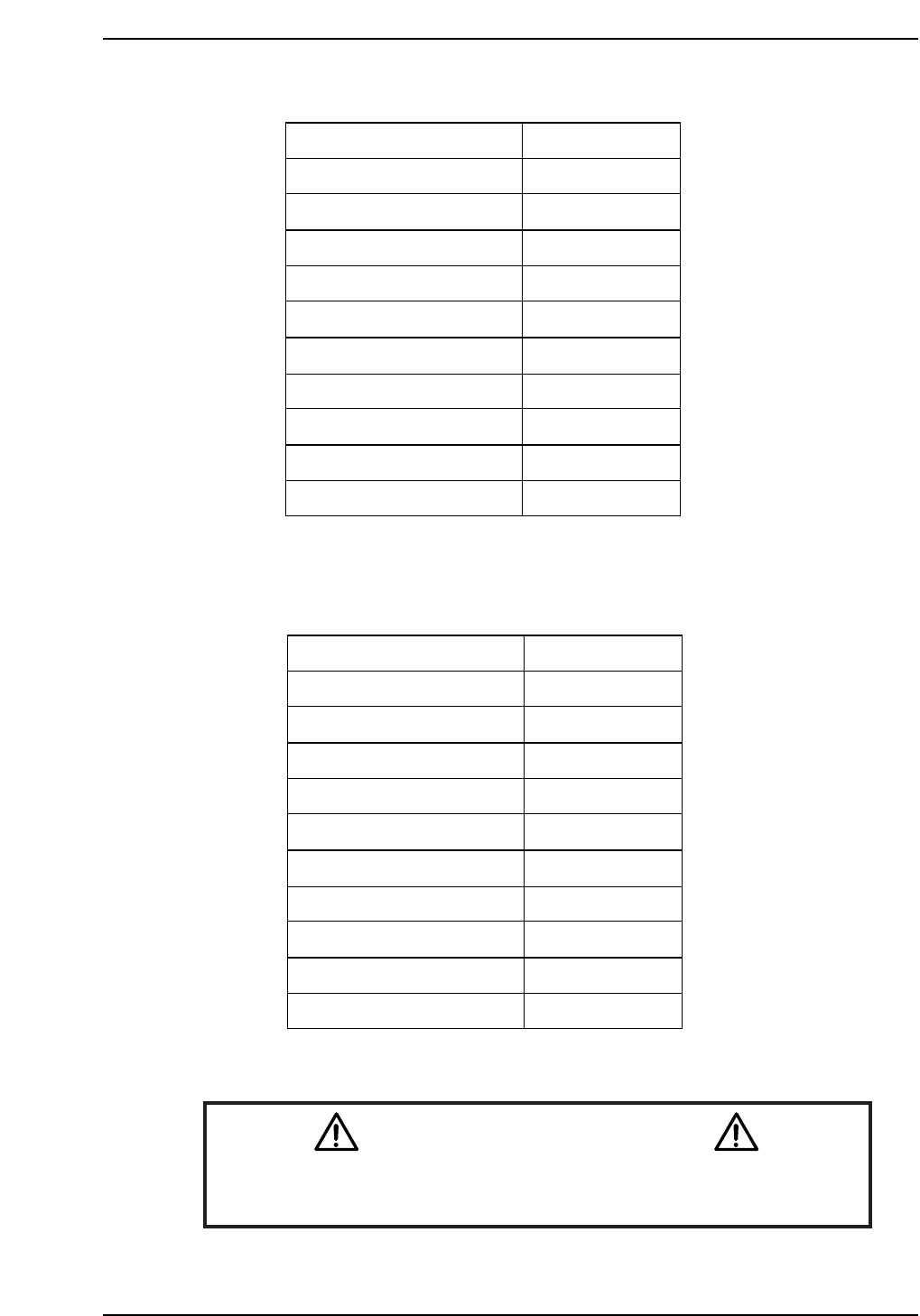
CP-732E Calibration Data Servo Count Chart (Y-axis)
CP-742E(ME) Calibration Data Servo Count Chart (Y-axis)
Caution
Ensure that new Calibration data is backed-up to the host computer
once the adjustment procedure is complete.
CN002
Plus mechanical stopper
+ OT sensor
Max limit pos.Y
Placing pos. Yø
Mark read pos. Yc
PCB check pos. Y
Loading pos. YL IN
Loading pos. YL OUT
Min limit pos. Y
- OT sensor ON
Minus mechanical stopper
241500 ± 1000
241000 ± 1000
240500 ± 1000
238500
226000
205000
2500
2500
0 ± 100
-500 ± 100
-2500 ± 100
CP7T31014
Plus mechanical stopper
+ OT sensor
Max limit pos.Y
Placing pos. Yø
Mark read pos. Yc
PCB check pos. Y
Loading pos. YL IN
Loading pos. YL OUT
Min limit pos. Y
- OT sensor ON
Minus mechanical stopper
195000 ± 1000
193000 ± 1000
192500 ± 1000
190000
175000
160000
2500
2500
0 ± 100
-500 ± 100
-2500 ± 100
CP7T31013

Chapter 1 1.4 Y-Axis Adjustments
Edition 2.0 1-16 CP-7-series Level 3 Tutorial
Notes:
Chapter 1 1.5 Replacing the Z-Motor
Edition 2.0 1-17 CP-7-series Level 3 Tutorial
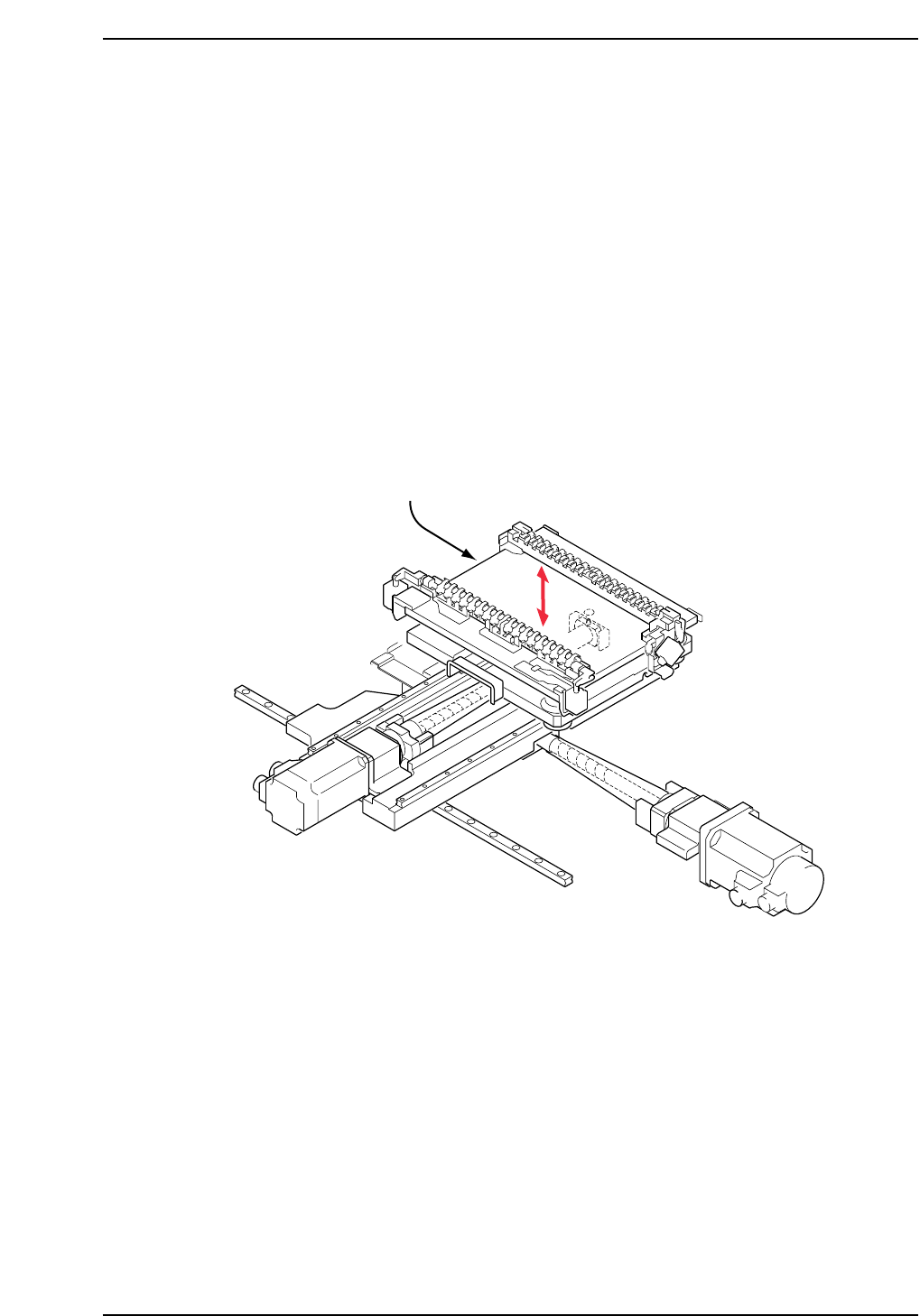
1.5 Replacing the Z-Motor
The Z-motor (refer to figure below) is responsible for moving the production table
down inside the machine in order to load and unload boards, and also to raise and
lower PCBs to the appropriate placing height based on the part height set in part
data.
A poorly adjusted or problematic Z-axis may prevent the PCB from being clamped
and unclamped properly when loading and unloading. It may also result in
damage to shafts or nozzles, or tombstoning of parts.
• Damage or slippage of the coupling that connects the Z-motor and the Z-axis ball
screw.
• After replacing the Z-motor
• After replacing the OT sensors, etc.
CP7T31015
Z-axis motor