00190725-01.pdf - 第10页
1.4 Pro gram Run a nd Op er ation • The AutoCal progr am of fer s the following possibilities: ➤ To perform a complete routine test of your m achine thereby determining most of t he machine data. To this end, all measuri…
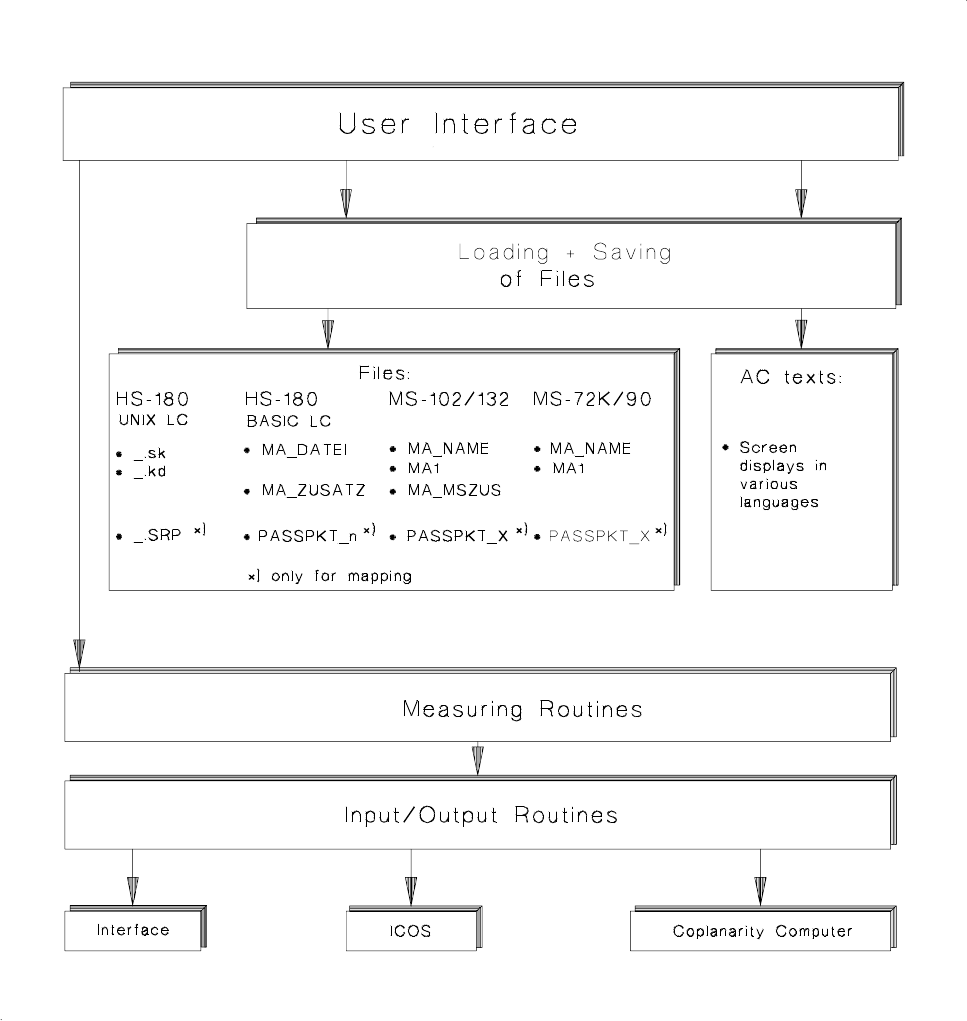
1.3 Program Architecture
Fig. 1.1 Program Architecture of AutoCal Program Version 114.xxx
User’s Manual AutoCal Program 1 Overview of the Program
Software Version 114.xxx 1.3 Program Architecture
1 - 3
1.4 Program Run and Operation
•
The AutoCal program offers the following possibilities:
➤ To perform a
complete routine test
of your machine thereby determining most of the machine data.
To this end, all measuring routines are executed in the specified sequence.
The time to be expended including mapping is approx. 5 hours for HS-180 placement stations and MS-
1xx; approx. 3 hours for the Adhesive Station II.
➤ To check and correct only individual machine data by means of
individual checks
(e.g. if errors have
occurred or following troubleshooting activities). When so doing, it is absolutely necessary to observe
the
interdependence
of machine data / calibrations in order to obtain valid MA-Data. All related infor-
mation is contained in chap. 6.
•
With some measuring routines the computer performs a plausibility check of the measured values follo-
wing the completion of the determination of the values and any errors are displayed on the screen. For a
very small number of values the operator assesses the measuring results according to the data contained
in the run description of the measuring routine.
•
Where a printer is connected, certain measuring results - except for the mapping results - are automat-
ically printed out. In the Mapping menu separate menu options are offered for the printout.
NOTE:
The MA-Data of the HS-placement station and adhesive station II as well as those of the MS-1xx machi-
ne must be correct within closely defined limits already before the calibration.
1.4.1 Overview of the File Versions and the Machine Selection Menu
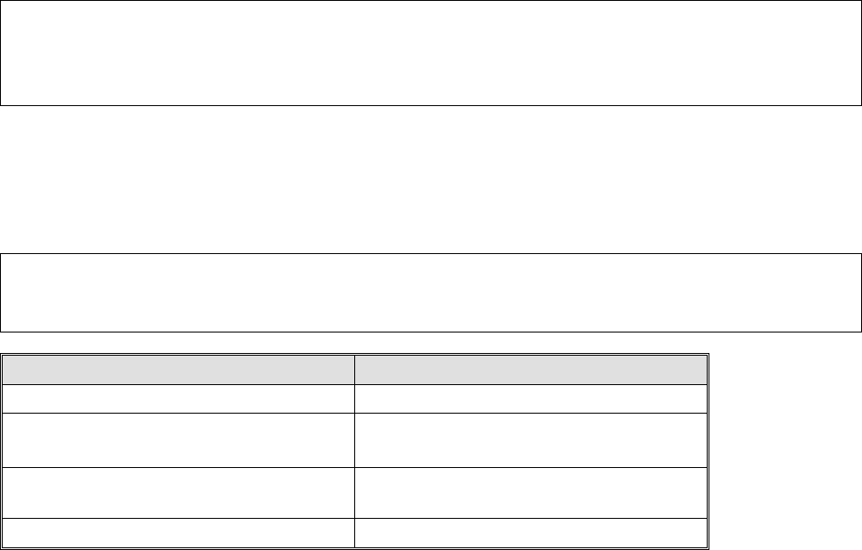
The table below shows the allocation of the line computer software versions to the MA-file versions that can
be selected from the Machine Selection menu.
NOTE
In the case of line computer software versions
<
10
2
.xxx it is recommended to get an UPDATE!
Line Computer Software Version MA-File Version
LRB.1XX.xxx V2.01
LRB.206.xxx
LRB.207.xxx
V2.03
LRB.208.xxx
LRB.209.xxx
V2.08
LRB.230.xxx V2.09
•
After the AutoCal program has been installed on the hard disk or started from diskette, as described in
chapter 4, first the following machine selection menu appears on HS-placement stations, adhesive stati-
ons II or MS-machines upon the start of the AutoCal program.
1 Overview of the Program User’s Manual AutoCal Program
1.4 Program Run and Operation Software Version 114.xxx
1 - 4

Machine Selection Menu:
Test HS-180 with SW V2.01 (ICOS 2)
Test HS-180 with SW V2.03 / 2.08 / 2.09 / UNIX ( ICOS 2 Q)
Test MS 102 (ICOS 2)
Test MS 102/128 (ICOS 2 Q)
Test MS 132 (ICOS 2)
Test MS 132 (ICOS 2 Q)
• When the correct machine type incl. the software version has been selected, the corresponding main
menu comprising the measuring routines available is displayed, as shown in Fig. 1.2.
NOTE
For measuring Adhesive Station II, "Test HS-180.." incl. the corresponding software version is to be selected.
1.4.2 Main Menu
• When the correct machine type incl. the correct software version has been selected, the respective main
menu comprising the measuring routines available is displayed (see Fig. 1.2).
• The size of the displayed main menu is dependent on the options predefined in the MA-Data:
The main menu, for instance, is displayed without the "Component camera menu" if no component came-
ra is defined in the MA-Data.
NOTE
For the performance of the complete routine check it is absolutely necessary that the sequence of
menu options as displayed on the screen be followed.
By keeping to this sequence it can be ensured that any interdependent calibrations / machine data are
automatically taken into consideration. This is a precondition for the validity of the data determined.
An exception is the "Glass mapping" and "Nozzle menu"→ see entries marked
2) 3)
in chart 1.2 on the fol-
lowing page.
• A number of measuring routines can be called up blockwise (identified in the figures on the following pa-
ges):
➤ If called up block-by-block, the PCB and calibration plate have only to be inserted once (= at the be-
ginning). The measuring routines will then be carried out successively and in the correct sequence.
➤ When the measuring routines are called up individually you are offered the possibility to check indivi-
dual machine positions, e.g. in the event of a fault or following troubleshooting activities.
NOTE:
When calling up the measuring routines individually, attention must be paid to interdependent calibrations
(see chap. 6).
User’s Manual AutoCal Program 1 Overview of the Program
Software Version 114.xxx 1.4 Program Run and Operation
1 - 5