00190725-01.pdf - 第55页
• TEST INPU TS After selecting "TEST INPUTS" the following s creen appears. SIEMENS CA LIBRATION PROGRAM AutoCal 114.xxx ST ATI ON 1 - ---- -------- ---- -------- ---- -------- ---- ---- -------- ---- -------- …
The inputs are also updated on the screen during the continuous run. Each input is checked
8 times before the output is changed again.
After selecting the continuous run, the label of function key F1 is changed to "CONT. OP. STOP".
Any change of the other outputs is no longer possible.
— The continuous run is terminated by pressing function key f1 once more.
— Actuating the "RESET" key causes all outputs to be set to zero. The "RESET" key is not active during
the continuous run.
Screen display after selecting "TEST OUTPUTS":
SIEMENS CALIBRATION PROGRAM AutoCal 114.xxx
STATION 1 ----------------------------------------------------------------------------------------------------------------------
INPUTS OUTPUTS
Bit 0 1 2 3 4 5 6 7 Bit 0 1 2 3 4 5 6 7
EF820 ( ) ( ) ( ) ( ) ( ) ( ) ( ) ( ) AF800 ( ) ( ) ( ) ( ) ( ) ( ) ( ) ( )
EF821 ( ) ( ) ( ) ( ) ( ) ( ) ( ) ( ) AF801 ( ) ( ) ( ) ( ) ( ) ( ) ( ) ( )
EF822 ( ) ( ) ( ) ( ) ( ) ( ) ( ) ( ) AF802 ( ) ( ) ( ) ( ) ( ) ( ) ( ) ( )
EF823 ( ) ( ) ( ) ( ) ( ) ( ) ( ) ( ) AF803 ( ) ( ) ( ) ( ) ( ) ( ) ( ) ( )
EF824 ( ) ( ) ( ) ( ) ( ) ( ) ( ) ( ) AF804 ( ) ( ) ( ) ( ) ( ) ( ) ( ) ( )
EF825 ( ) ( ) ( ) ( ) ( ) ( ) ( ) ( ) AF805 ( ) ( ) ( ) ( ) ( ) ( ) ( ) ( )
EF826 ( ) ( ) ( ) ( ) ( ) ( ) ( ) ( ) AF806 ( ) ( ) ( ) ( ) ( ) ( ) ( ) ( )
EF827 ( ) ( ) ( ) ( ) ( ) ( ) ( ) ( ) AF807 ( ) ( ) ( ) ( ) ( ) ( ) ( ) ( )
AF808 ( ) ( ) ( ) ( ) ( ) ( ) ( ) ( )
AF809 ( ) ( ) ( ) ( ) ( ) ( ) ( ) ( )
ATTENTION! SETTING COMPETING OUTPUTS SIMULTANEOUSLY MAY RESULT DAMAGE!
TO CHANGE AN OUTPUT, PRESS <Return>
➤ When setting outputs, pay attention to the WARNING on page 11!
CONT. OP.
START
RESET
END
5 Description of the Menu Options User’s Manual AutoCal Program
5.1 Description of the Menu Options for HS-180 Placement Stations Software Version 114.xxx
5 - 12
•
TEST INPUTS
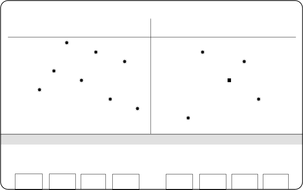
After selecting "TEST INPUTS" the following screen appears.
SIEMENS CALIBRATION PROGRAM AutoCal 114.xxx
STATION 1 ----------------------------------------------------------------------------------------------------------------------
TEST INPUTS
EF821.1=1 EF821.1=0 EF821.1=1 EF821.1=0 EF821.1=0
EF821.1=0 EF821.1=1 EF821.1=0 EF821.1=1 EF821.1=0
EF825.5=1 EF825.5=0 EF825.5=1 EF825.5=0 EF825.5=0
EF824.7=1
In the view area, which is delimited by two lines, all changes of the status changes of the inputs are dis-
played. Use function key f1 for "CLEAR DISPLAY" to delete the inputs displayed.
5.1.22 STORING
The values determined can be saved from the main memory to the work diskette by selecting this menu opti-
on available on the main menu and the EDIT menu.
A save should be performed after each measuring routine so as to preclude any data loss due to any malfun-
ctions that might occur.
If the work diskette containing the machine data is write protected, the software will issue the following mes-
sage after "STORING" has been selected:
"NO SPACE TO STORE".
This is, however, not the case. Deactivate the write protect tab on the work diskette and select "STORING"
once more.
CLEAR
DISPLAY
END
User’s Manual AutoCal Program 5 Description of the Menu Options
Software Version 114.xxx 5.1 Description of the Menu Options for HS-180 Placement Stations
5 - 13
5.2 Description of the Menu Options for HS-180 Adhesive Station II
5.2.1 EDIT MENU
After selecting the "EDIT MENU" the submenu appears (see Fig. 1.6).
The description of this menu is contained in section 5.1.1
5.2.2 CHECK AXIS ADJUSTMENT
The description of this menu option is contained in section 5.1.2
On the Adhesive Station II the axis adjustment test for the X and Y-axes is possible.
5.2.3 MEASURE MACHINE ZERO POINT
This measuring routine is used to determine the X and Y-zero point
correction
values of the MA zero point.
Just as is the case on other machines, this is carried out by means of the MA zero point gauge. For the pur-
pose of this measuring routine, the adhesive station zero point gauge is installed in the adhesive application
head in lieu of the right adhesive cartridge.
The description of this menu option is contained in section 5.1.3
➤ Pay attention to the WORKAROUND pertaining to this menu option → section 12.3
5.2.4 PCB EDGE FIXED TABLE
This measuring routine is used to determine the "PCB EDGE FIXED TABLE Y" value. To this end, first the
Bero switching point is determined and is then displayed on the screen together with the internally calculated
"PCB EDGE FIXED TABLE " value.
The "PCB EDGE FIXED TABLE " value is required within the scope of the AutoCal measuring sequence as
well as during the placement cycle as starting value (see description of this menu option in section 5.1.7.
5.2.5 MAPPING MENU
Mapping is used for the automatic measurement of the gantry offset.
The Mapping menu is only offered if a head camera is activated on the Adhesive Station II.
Mapping is carried out by measuring the
glass
mapping plate.
Prior
to the
glass
mapping sequence the
head camera
must be
calibrated
(see menu options 5.2.7 and
5.2.8) !
After selecting the "Mapping menu" a
submenu
(see Fig. 1.7) is displayed.
Carry out the menu functions proceeding in the sequence as shown on the screen
.
5 Description of the Menu Options User’s Manual AutoCal Program
5.2 Description of the Menu Options for HS-180 Adhesive Station II Software Version 114.xxx
5 - 14