00190725-01.pdf - 第15页
A short description of the above submenus is cont ained on the following page! Fig . 1 .5 Sub me nus of HS -18 0 P lac em en t St ati on Us er’ s Ma nual Auto Cal Prog ram 1 Ov erv iew of th e Pr ogr am Sof tw are Ver si…
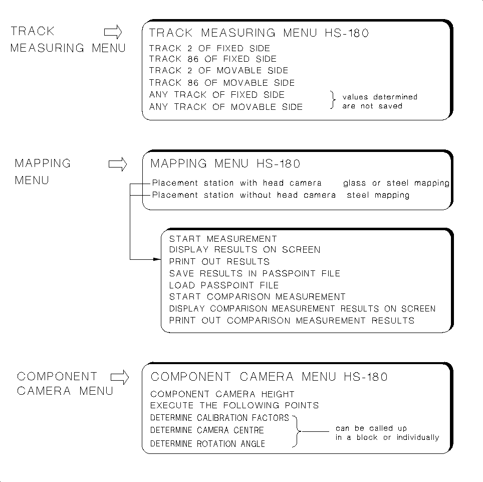
These submenus are designed to determine MA-Data and the gantry offset
• In the
TRACK MEASURING MENU
the X,Y and Z-values of the tracks of the fixed and movable table si-
des are determined.
• The
MAPPING MENU
for HS-180 placement stations offers different measuring sequences, depending
on the options available: If a head camera (PCB camera) is activated, you can select between "Glass
mapping" or "Steel mapping". If not, only the measuring sequence for "steel mapping" is available. The re-
spective mapping plate must be available (see "Testing Aids", chap. 3).
— A precondition for "Glass mapping" is the calibration of the head camera (see Fig. 1.2).
• The
COMPONENT CAMERA MENU
allows you to call up a number of measuring routines either blockwi-
se or individually. In this connection, pay attention to the information contained in section 1.4.2.
Fig. 1.4 Submenus of HS-180 Placement Station
1 Overview of the Program User’s Manual AutoCal Program
1.4 Program Run and Operation Software Version 114.xxx
1 - 8
A short description of the above submenus is contained on the following page!
Fig. 1.5 Submenus of HS-180 Placement Station
User’s Manual AutoCal Program 1 Overview of the Program
Software Version 114.xxx 1.4 Program Run and Operation
1 - 9

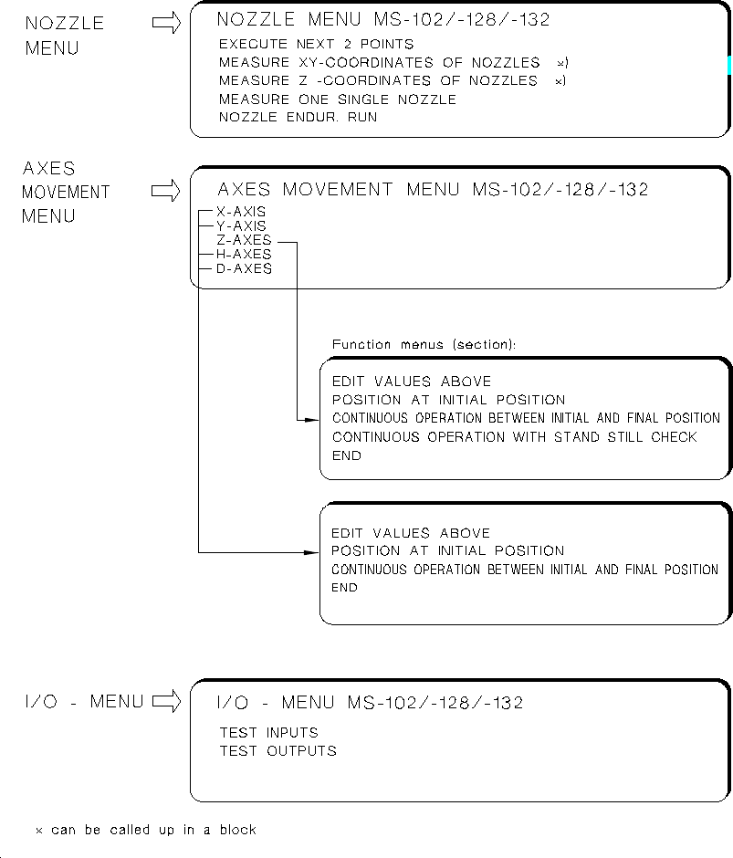
These submenus are designed for the determination of MA-Data, adjustment of axes or testing inputs
and outputs:
•
NOZZLE MENU:
Serves to determine all X,Y and Z-nozzle positions, either for all X,Y or all Z-positions
within a measuring sequence, or explicitly by selection for individual nozzles only. Moreover, the "conti-
nuous nozzle run" allows you to check the pick-up and depositing procedure for nozzles.
•
AXES MOVEMENT MENU:
These functions allow you to check the movement / positioning of individual
axes in the event of a malfunction and to perform the adjustment of the axes, if required.
For the Z-axis the continuous run function including standstill control and the force values are offered on
the functions menu in addition (see chap. 5 "Description of the Menu Options").
Selecting the continuous run function of the Y-axis causes the left table side to be approached and the
possible traversing range to be determined.
NOTE
∆
!
∆
!
For the adjustment of an axis the documentation pertaining to the adjustment of axes is required in ad-
dition.
•
I/O MENU:
This menu permits you to set the desired outputs by selecting "TEST OUTPUTS", to toggle
the outputs by selecting "ENDURANCE RUN" and to read the updated inputs in each case off the screen
when so doing. Selecting "TEST INPUTS" causes all signal state changes of the inputs to be displayed
successively on the screen.
Further information on the I/O Menu is contained in chap. 5.
WARNING
∆
!
∆
!
Any concurrent setting of competing outputs may result in damage to the machine!
N o (!) verification by the software is carried out !
1 Overview of the Program User’s Manual AutoCal Program
1.4 Program Run and Operation Software Version 114.xxx
1 - 10