00190725-01.pdf - 第12页
Legend: = displayed / ex ecut able mai n men u opt ion of the respectiv e machine type. Execution of the menu options is performed in the sequence displayed on t he screen (see )! = w hen this menu option is selec ted, a…

Machine Selection Menu:
Test HS-180 with SW V2.01 (ICOS 2)
Test HS-180 with SW V2.03 / 2.08 / 2.09 / UNIX ( ICOS 2 Q)
Test MS 102 (ICOS 2)
Test MS 102/128 (ICOS 2 Q)
Test MS 132 (ICOS 2)
Test MS 132 (ICOS 2 Q)
• When the correct machine type incl. the software version has been selected, the corresponding main
menu comprising the measuring routines available is displayed, as shown in Fig. 1.2.
NOTE
For measuring Adhesive Station II, "Test HS-180.." incl. the corresponding software version is to be selected.
1.4.2 Main Menu
• When the correct machine type incl. the correct software version has been selected, the respective main
menu comprising the measuring routines available is displayed (see Fig. 1.2).
• The size of the displayed main menu is dependent on the options predefined in the MA-Data:
The main menu, for instance, is displayed without the "Component camera menu" if no component came-
ra is defined in the MA-Data.
NOTE
For the performance of the complete routine check it is absolutely necessary that the sequence of
menu options as displayed on the screen be followed.
By keeping to this sequence it can be ensured that any interdependent calibrations / machine data are
automatically taken into consideration. This is a precondition for the validity of the data determined.
An exception is the "Glass mapping" and "Nozzle menu"→ see entries marked
2) 3)
in chart 1.2 on the fol-
lowing page.
• A number of measuring routines can be called up blockwise (identified in the figures on the following pa-
ges):
➤ If called up block-by-block, the PCB and calibration plate have only to be inserted once (= at the be-
ginning). The measuring routines will then be carried out successively and in the correct sequence.
➤ When the measuring routines are called up individually you are offered the possibility to check indivi-
dual machine positions, e.g. in the event of a fault or following troubleshooting activities.
NOTE:
When calling up the measuring routines individually, attention must be paid to interdependent calibrations
(see chap. 6).
User’s Manual AutoCal Program 1 Overview of the Program
Software Version 114.xxx 1.4 Program Run and Operation
1 - 5
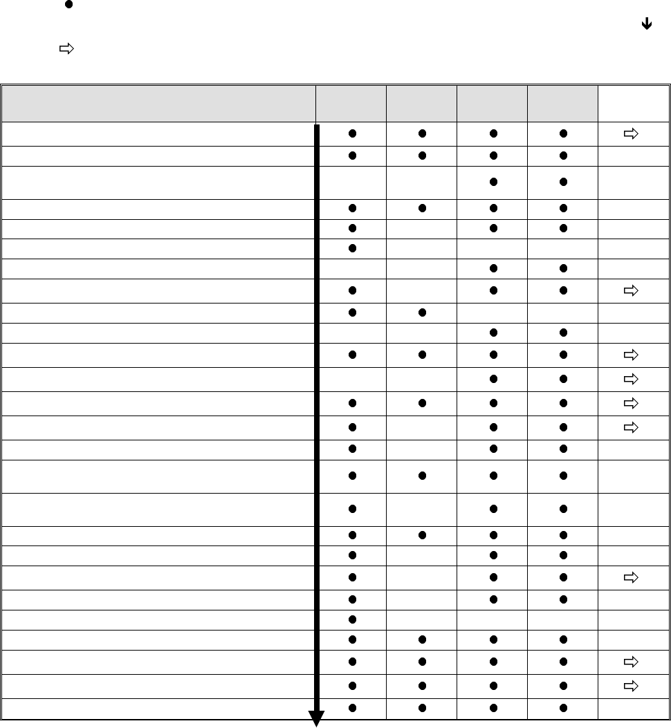
Legend: = displayed / executable main menu option of the respective machine type.
Execution of the menu options is performed in the sequence displayed on the screen (see )!
= when this menu option is selected, a submenu is displayed as shown for the respective machine
types in figures 1.3 to 1.11.
1)
These measuring routines can be called up either individually or in a block by selecting "EXECUTE NEXT
4 POINTS". In this connection, please take note of the text on page 1-5!
2)
Prior
to the performance of "Glass mapping" (adhesive station II and HS-180 placement station), "DETERMINE
CALIBRATION FACTORS OF HEAD CAMERA" and "DETERMINE CAMERA OFFSET" are to be carried
out in the specified sequence.
3)
Prior
to the execution of the "NOZZLE MENU" the option "DETERMINE ANGLE CORRECTION OF D-AXIS"
has to be carried out.
Functions for machine type: Placem.st
HS-180
Adh.st.II
HS-180
MS-102
MS-128
MS-132
Submenu
EDIT MENU
CHECK AXIS ADJUSTMENT
DETERMINE MAX. AND MIN. Z-AXIS
TRAVEL RANGES
----- -----
MEASURE MACHINE ZERO POSITION
DETERMINE ECCENTRICITY OF NOZZLE
-----
DETERMINE HEAD HEIGHT
----- ----- -----
REGISTER PLACEMENT LEVEL Z AXIS
----- -----
TRACK MEASURING MENU
-----
DETERMINE PCB EDGE FIXED TABLE
----- -----
DETERMINE SENSOR MOVABLE TABLESIDE
-----
MAPPING MENU (Glass /Steel Mapping)
2)
ADHESIVE MENU
----- -----
AXES INITIALIZING MENU
NOZZLE MENU
-----
EXECUTE NEXT 4 POINTS
-----
DETERMINE CALIBRATION FACTORS OF
HEAD CAMERA
1)
2)
DETERMINE ANGLE CORRECTION OF
D-AXIS
1)
3)
-----
DETERMINE CAMERA OFFSET
1) 2)
DETERMINE JAW OFFSET
1)
-----
COMPONENT CAMERA MENU
-----
DETERMINE COPLANARITY COORDINATES
-----
MEASURE ANY HOLE (REPEATEDLY)
----- ----- -----
CONVEYOR BELT WIDTH ADJUSTMENT
AXES MOVEMENT MENU
I/O MENU
STORING
Fig. 1.2 Main Menu of the Various Machine Types (Maximum Configuration)
1 Overview of the Program User’s Manual AutoCal Program
1.4 Program Run and Operation Software Version 114.xxx
1 - 6
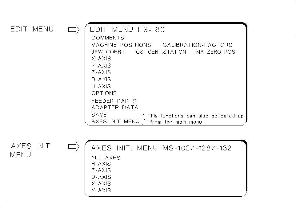
1.4.3 Submenus for HS-180 Placement Stations
The display of the submenus is dependent - similarly to the main menu - on the options activated. For details
on these submenus → refer to chap. 5 "Description of the Menu Options for HS-180 Placement Stations".
These submenus are designed for
checking and correcting MA-data.
• The
EDIT MENU
allows you to enter the data that cannot be determined automatically (e.g. zero point cor-
rection values of the axes) directly into the MA-data and to initialize the axes directly from the Edit Menu.
• Upon starting the AutoCal program: If you have to respond to the first query "Z AXIS IN UPPER POSI-
TION?" with NO, the main menu is displayed from which the EDIT MENU can be selected enabling you
to check / edit the correction values of the axis and to initialize the axes.
• Under "Options" you can review the activation of a given option, yet no changes can be made.
• Under "ADAPTER DATA" you can (with the
Nozzle changer
activated) obtain a display of the X, Y and Z-
pick-up positions of the nozzles, the adapter lengths and the Z-position following the pick-up of the adapters.
• Within the measuring sequence of the routine check, call up the EDIT MENU to check, for instance,
the "min. / max. X and Y-travel paths" and to correct them, if required, in accordance with the measu-
ring sequence description.
• From the EDIT MENU it is also possible to call up the AXES INIT MENU (see submenu) to ensure, for instance,
the troublefree performance of the axes reference run prior to the selection of the first measuring routine.
• The
AXES INITIALIZING MENU
enables you to initialize either individual or all axes.
Fig. 1.3 Submenus of HS-180 Placement Station
User’s Manual AutoCal Program 1 Overview of the Program
Software Version 114.xxx 1.4 Program Run and Operation
1 - 7