EUKYX-199-2100_G5S2_Instruction_Vol2_E.pdf - 第110页
EUKYX 1-60 199-2100 5. "Prod.Dt." Submenu 5 . " P rod .Dt . " Subme nu Graphic Development MTN:NotRdy RCG:NotRdy MTN:NotRdy RCG:NotRdy F2A46 The "Prod.Dt. " submenu i s provided with the fol…
EUKYX
1-59199-2100
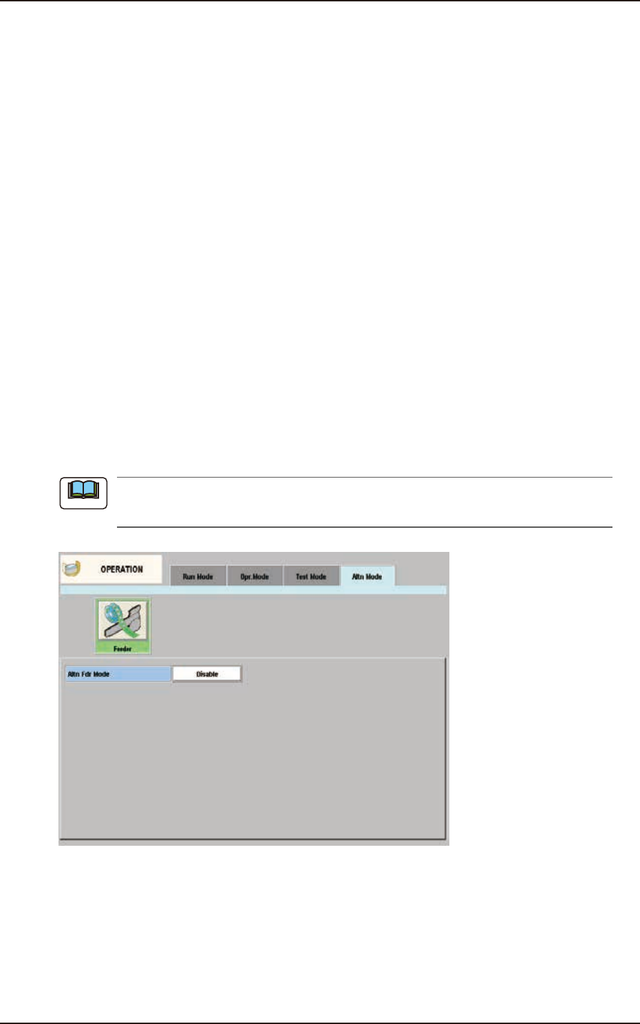
4.4 "Altn Mode" Tab Sheet
[2] F1 and F2
The feeder Nos. and the destination feeder Nos. are colored, indicating whether the alternate feeder
mode is “enabled” or “disabled”.
Light Blue : Enable
Pink : Disable
"Disable" is automatically set for the feeder No. where a component shortage error is detected.
When a feeder is set after component replenishment, "Enable" is automatically set.
[3] "Set Data" Group Box
The Feeder No. selected in [2] appears in the "Fdr No." text box.
[Enable] and [Disable] Buttons
When the feeder whose parameter "Enable" or "Disable" for the feeder alternate function
must be changed is selected and the [Enable] or the [Disable] button is pressed, the
parameter can be changed manually.
[Enable All F1] Button, [Enable All F2] Button
"Enable" is set for all feeders on the feeder base selected in [2] (Feeder Base #1 in the
window).
[Jump to Alt Fdr] Button
The feeder Nos. selected in [2] are specified as the destination ones for the alternate feeder
mode.
Comp ID, Type, and Dir
Displayed are the component ID, type and angle of the feeder No. selected in [2].
When “Disable” is set for the alternate feeder mode in the pattern program, the “Altn Mode”
window is changed as follows.
F2A45
Note
EUKYX
1-60199-2100
5. "Prod.Dt." Submenu
5. "Prod.Dt." Submenu
Graphic
Development
MTN:NotRdy RCG:NotRdy
MTN:NotRdy RCG:NotRdy
F2A46
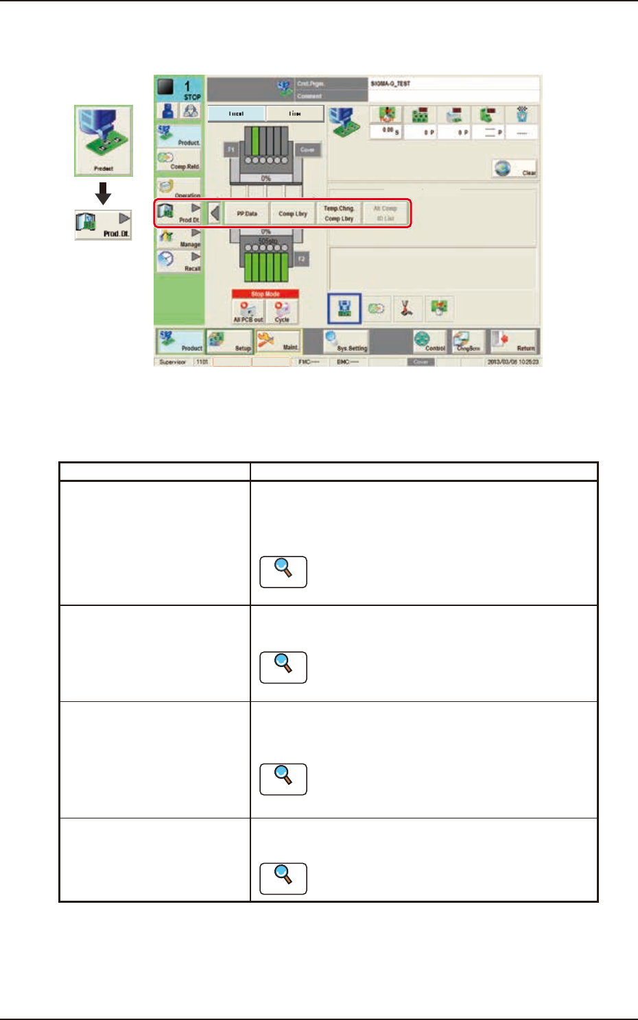
The "Prod.Dt." submenu is provided with the following three menu items. When each button is
pressed, the corresponding window appears.
Please fully understand the purposes of each data for better performance of the machine.
Buttons Description
PP.Da t a Pattern programs must be created for each PCB to be
produced.
The automatic operation of this machine is controlled by
these pattern programs.
Reference
Refer to “Chapter 2 Pattern Program” for details.
Comp Lbry This library stores data related to picks, recognition, and
placement of each individual component.
Reference
Refer to “Chapter 3 Component Library” or “Volume
6 : Component Library” for the details.
Temp.Chng.Comp Lbry The corresponding tab window enables the operator to
change the component library temporarily during the
automatic operation.
Reference
Refer to “2. “Temp Chng Comp Lib” Window” in
Chapter 3 or “Volume 6 : Component Library” for
the details.
Alt Comp ID List The corresponding window is used to setup the alternative
components in placed of the current components.
Reference
Refer to “3. “Alt Comp ID List” Window” in Chapter
3 for details.
EUKYX
1-61199-2100
6. "Manage" Submenu
6. "Manage" Submenu
Graphic
Development
MTN:NotRdy RCG:NotRdy
F2A47
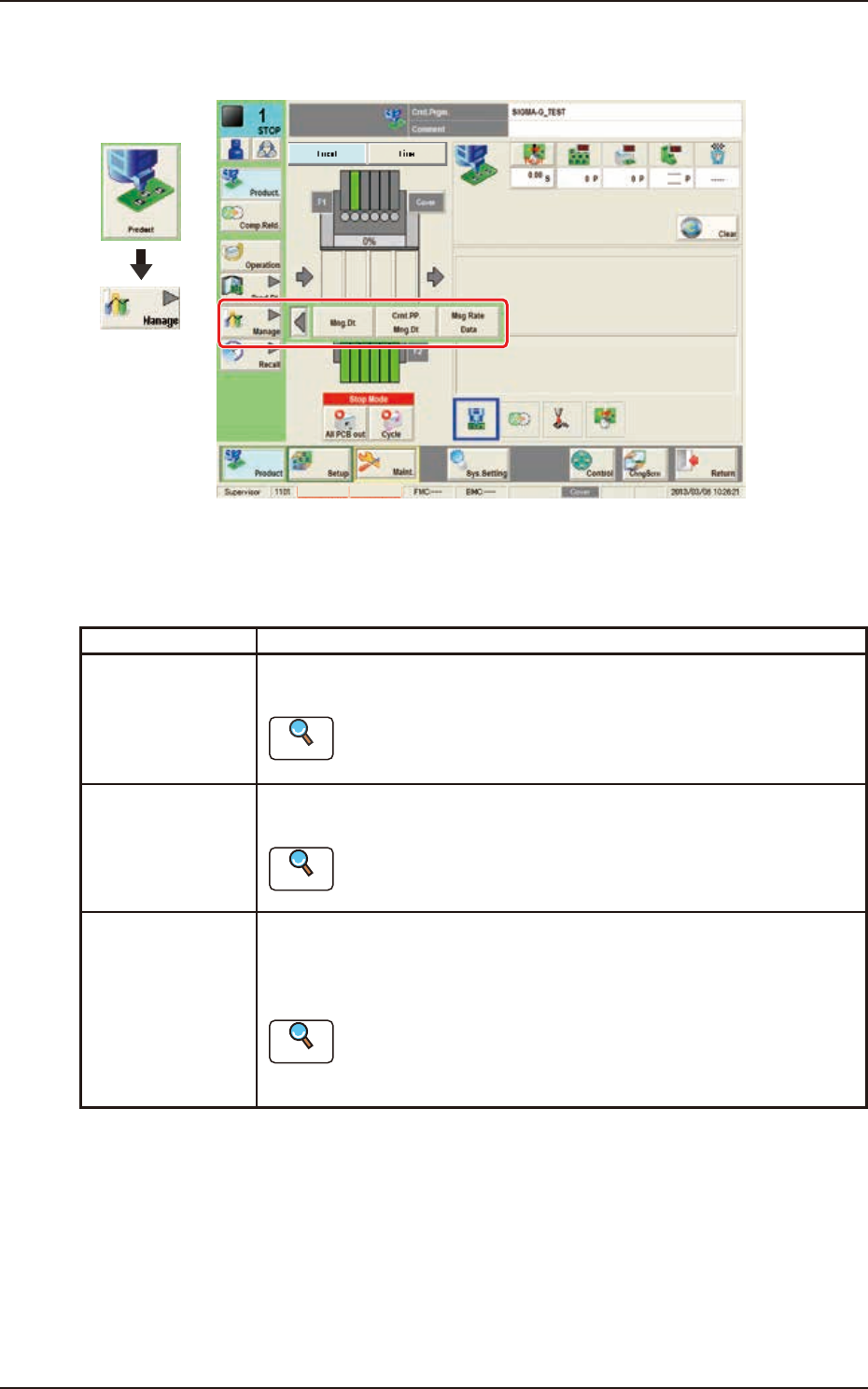
The "Manage" submenu is provided with the following three buttons.
When a button is pressed, the corresponding window opens, enabling the operator to select the
required data.
Buttons Description
Mng.Dt. When pressed, the "Management Data" window is displayed and operated for
totaling the management data for the whole system.
Reference
Refer to “2. “MNG.DT.” Window” in Chapter 4 for the details.
Crnt.PP.Mng.Dt When pressed, the "Crnt.PP.Mng.Dt" window is displayed and operated for
totaling the current pattern program management data for each pattern program.
Reference
Refer to”3. “CRNT.PP.MNG.DT” Window” in Chapter 4 for the details.
Msg Rate Data When pressed, the "Msg Rate Data" window is displayed and operation for
displaying the component handling error rate managed for each feeder or nozzle
based on each component handling error rate specified in the operation
parameter setting.
Reference
Refer to”4. “MESSAGE.RATE.DT” Window” in Chapter 4 for the
details.