EUKYX-199-2100_G5S2_Instruction_Vol2_E.pdf - 第119页
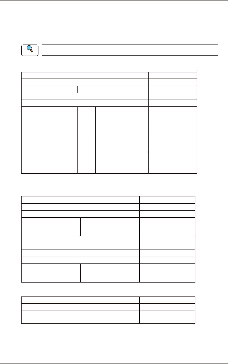
EUKYX 2-6 199-2100 2.3 Composition of Operation Data C04 Set -up Dat a Items R ef. No . Con veyor (C0 4_01 ) C05 Suppor t Pin Data Items R e f. N o. Sup po r t Pin Se t ( C 0 5 _ 01) Sup p or t Pi n (C05 _02 ) The n umb …
EUKYX
2-5199-2100
2.3 Composition of Operation Data
2.3 Composition of Operation Data
The set parameters are used to manage the overall pattern program data.
This data is composed of the PCB data, the PEC recognition data, the PEC recognition mark data,
and the setup data.
Refer to “3.3 Operation” in this chapter for the details of earth item.
C01 Function Data
Items Ref. No.
PEC recognition function
(C01_01)
All Zones 1 to 5
(C01_02)
Image
(C01_03)
Local
(C01_04)
Zones 1 to 5 #1 X [mm] (Horizontal) Y
[mm] (Vertical)
Mark Code
(C01_05)
#2 X [mm] (Horizontal) Y
[mm] (Vertical)
Mark Code
#3 X [mm] (Horizontal) Y
[mm] (Vertical)
Mark Code
C02 PEC Recognition Mark Data
Items Ref. No.
Mark No. (C02_01)
Mark Ty pe (C02_02)
Mark Size D1
D2
D3
(C02_03)
Window Size (C02_04)
Mark Image (C02_05)
Mark Level (C02_06)
Angle (C02_07)
Lighting Level Coax
Ring
Option
(C02_08)
C03 Operation Data
Items Ref. No.
PEC Recognition Set (C03_01)
Beam (C03_02)
Sequence (C03_03)
Reference

EUKYX
2-7199-2100
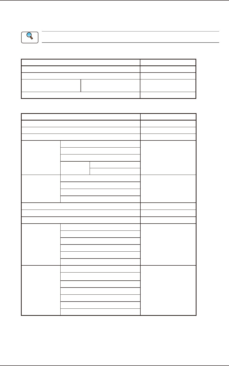
2.4 Composition of Control Data
2.4 Composition of Control Data
The set parameters are used to set automatic operation and PCB transfer control.
Refer to 3.4 Control in this chapter for the details of each item.
D01 Control Data
Items Ref. No.
Placement Mode (D01_01)
PCB Finishing Position (D01_02)
Pre-PL cmpnt thkns CB Top
PCB Bottom
(D01_03)
PEC expansion correction (D01_04)
D02 PCB Locate Data
Items Ref. No.
PCB detection off DLY (D02_01)
PCB Locate SET (D02_02)
PCB Locate Sequence (D02_03)
UP MOVE (D02_04)
1st Speed DCLR SET
2nd Speed DCLR SET
Z Clamp Opr. waiting time
Opr. ST DLY timer
DN MOVE (D02_05)
1st Speed DCLR SET
2nd Speed DCLR SET
Backup axis DN start DLY
SW POSN of 1st / 2nd (D02_06)
Replace vacuum sensor (D02_07)
PCB position of contact (D02_08)
UP MOVE (D02_09)
1st speed DCLR SET
2nd speed DCLR SET
Vac. Ctrl. delayed starts
Vac. Wtg. Timer
Z clamp waiting time
DN MOVE (D02_10)
1st speed DCLR SET
2nd speed DCLR SET
Vac. Ctrl. delayed starts
Vac. Wtg. Timer
Damaged Vac. Wtg. time
Backup axis DN start DLY
Reference