EUKYX-199-2100_G5S2_Instruction_Vol2_E.pdf - 第245页
EUKYX 6-8 199-2100 4. "CNVR Set-up" Window [ 3] "PCB Supp ort Pins " G roup Box [Reset PCB Sup.Pins ] But t on When the [ ST ART] but ton is pressed withi n 1 0 seconds af ter thi s but ton is p resse…
EUKYX
6-7199-2100
4. "CNVR Set-up" Window
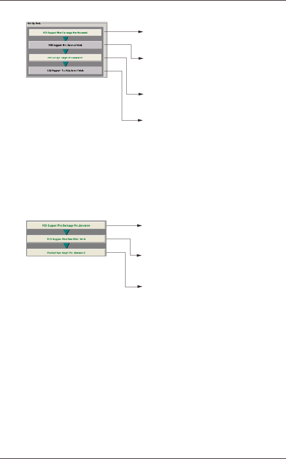
• For Support Pin Manual Change
• When the [START] button is pressed within 10 seconds
after this button is pressed, the head retracts and
the conveyor width becomes the maximum one.
• When the [START] button is pressed within 10 seconds
after this button is pressed, the conveyor width is changed
according to the PCB size Y that is set to pattern program.
• When the [START] button is pressed within 10 seconds
after pressing the [Locate] button in the "PCB Locate"
group box, the support base starts moving up.
• Press the [COVER] button at the bottom of window to unlock
the cover. Open the cover to arrange support pins and then
close the cover.
• Press the [START] button in 10 seconds after pressing the
[Release] button in the "PCB Locate" group box.
The backup base starts moving down.
PCB Support Pins Rem. Work
• Press the [COVER] button at the bottom of window to unlock
the cover. Open the cover to collect support pins and then
close the cover.
PCB Support Pins Attachment Work
F2F8
• For Support Pin Automatic Change
• When the [START] button is pressed within 10 seconds
after this button is pressed, the head retracts and
the conveyor width becomes the maximum one.
• When the [START] button is pressed within 10 seconds
after this button is pressed, the support pin automatic
setup is performed according to the pattern program.
• When the [START] button is pressed within 10 seconds
after this button is pressed, the conveyor width is moved
to the production position.
F2F9
[2] "Noz Chg." Group Box
[Reset] Button
When this button is pressed and within 10 seconds, the [START] button on the operation
panel is pressed, the support pins are housed in the nozzle area.

EUKYX
6-8199-2100
4. "CNVR Set-up" Window
[3] "PCB Support Pins" Group Box
[Reset PCB Sup.Pins] Button
When the [START] button is pressed within 10 seconds after this button is pressed, the
support pins are housed in the stock area.
[Stkr.Area Edit] Button
In the case that the PCB support pins are to be moved manually or an error occurs, the stock
area parameters are edited.
When the [Stkr.Area Edit] button is pressed, the "Stkr.Area Edit" window appears.
Refer to “4.2 “Stkr.Area Edit” Window” for the details of the "Stkr.Area Edit" window.
[4] PCB Locate Section Select Buttons
When pressed, the PCB positioning section on the side where the setup operation is to be
performed, is selected.
[Side L] Button : PCB Locate L Section
[Side R] Button : PCB Locate R Section
[5] "PCB Locate" Group Box
[Locate] Button :
When pressed, this button moves up the Z clamp and the backup base
and locates the PCB.
[Release] Button :
When pressed, this button moves down the Z clamp and the backup
base and releases the PCB locating.
[6] "Conveyor Width" Group Box
PCB Size Y, Y Standard Pos.
The "PCB size Y" and "Y Standard Pos." set on the pattern program data for the product
model, are shown in these data boxes.
[Clearance] Button
When this button is pressed, the "Clearance" window opens. Enter the value as a leeway
between the conveyor width and the PCB. The entered value appears in the text box beside
this button. The actual conveyor width becomes "PCB Size Y + Clearance (Recommended
Value: 0.5 mm)".
Reference
EUKYX
6-9199-2100
4.1 Collecting PCB Support Pins/Setting up Conveyor Width
4.1 Collecting PCB Support Pins/Setting up Conveyor Width
• For Support Pin Manual Change
The PCB support pins are used to keep the upper surface of the PCB in proper height for
stabilization of the component placement. If the conveyor width is not correctly set, the PCB
support pins cannot be attached correctly.
When 0402 and 0603 components must be placed, it is important to secure the flatness of the
PCB. Use the support pins or a backup plate.
Contact YAMAHA sales representatives for how to make a backup plate.
CAUTION
The load power to the motors, etc., is turned
OFF but the setup operation must be performed
carefully when you put your hand inside the
machine. Avoid hand and nger injuries.
(1)
Press the [Setup] button and [CNVR Set-up] button to display the “CNVR Set-up SPRT-PINS“
window.
MTN:NotRdy RCG:NotRdy Cover
F2F10
(2)
Press the [PCB Support Pins Exchange Pos. Movement] button.
After that, press the [START] button on the operation panel within 10 seconds (The machine
retracts the head and maximizes the conveyor width.)
(3) Press the “cover” to unlock the cover.
Cover
Cover
F2F10A
Note
Procedure