EUKYX-199-2100_G5S2_Instruction_Vol2_E.pdf - 第271页
EUKYX 6-34 199-2100 7.2 "Place Pos T each" Window 7 .2.3 Placement Po sition T each Operation Procedure The followi ng de scribes the procedure based on the assu mptio n that "F ront Ri gh t" is selec…
EUKYX
6-33199-2100
7.2 "Place Pos Teach" Window
7.2.2 "Recognition" Window in Manual Alignment Mode
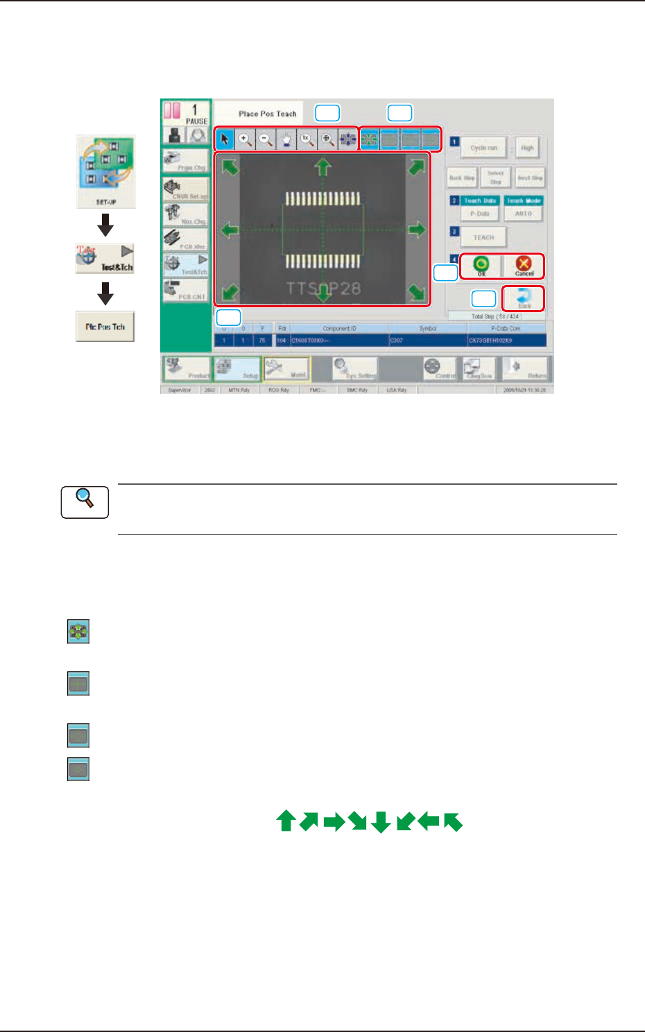
When any of the [Cycle run] button, [Select Step] button or [TEACH] button is pressed, the
following window appears.
[1] [2]
[3]
[4]
[5]
Graphic
Development
F2F39
[1] Image Operation Buttons
The following buttons can be used to change the mode that enlarges or moves the image in the
recognized image display area.
Refer to "[3] Image Operation Buttons" in “7.2.1 “Recognition” Window for Placement Position
Teaching” for the description of each button.
[2] Graphics Selection Buttons
Use these button to select the types of a graphic to be displayed for the manual alignment
operation. (Multiple Selection Acceptable)
[
] Button : This button is used when the displayed image position is aligned with the graphic
image position.
[
] Button : When selected, this button displays a crosshair that indicates the center of the
camera.
[
] Button : When selected, this button displays the scale lines.
[
] Button : When selected, this button displays the outline of the object mark for the manual
alignment.
[3] Graphic Image Move Buttons (
Buttons)
When the arrow direction is touched in the recognition image display area, the image is moved in
the corresponding direction.
[4] [OK] Button
When pressed, the matching position is confirmed.
[Cancel] Button
When pressed, this button cancels the manual alignment operation.
[5] [Back] Button
When pressed, the window returns to “Place Pos Teach” window.
Reference
EUKYX
6-34199-2100
7.2 "Place Pos Teach" Window
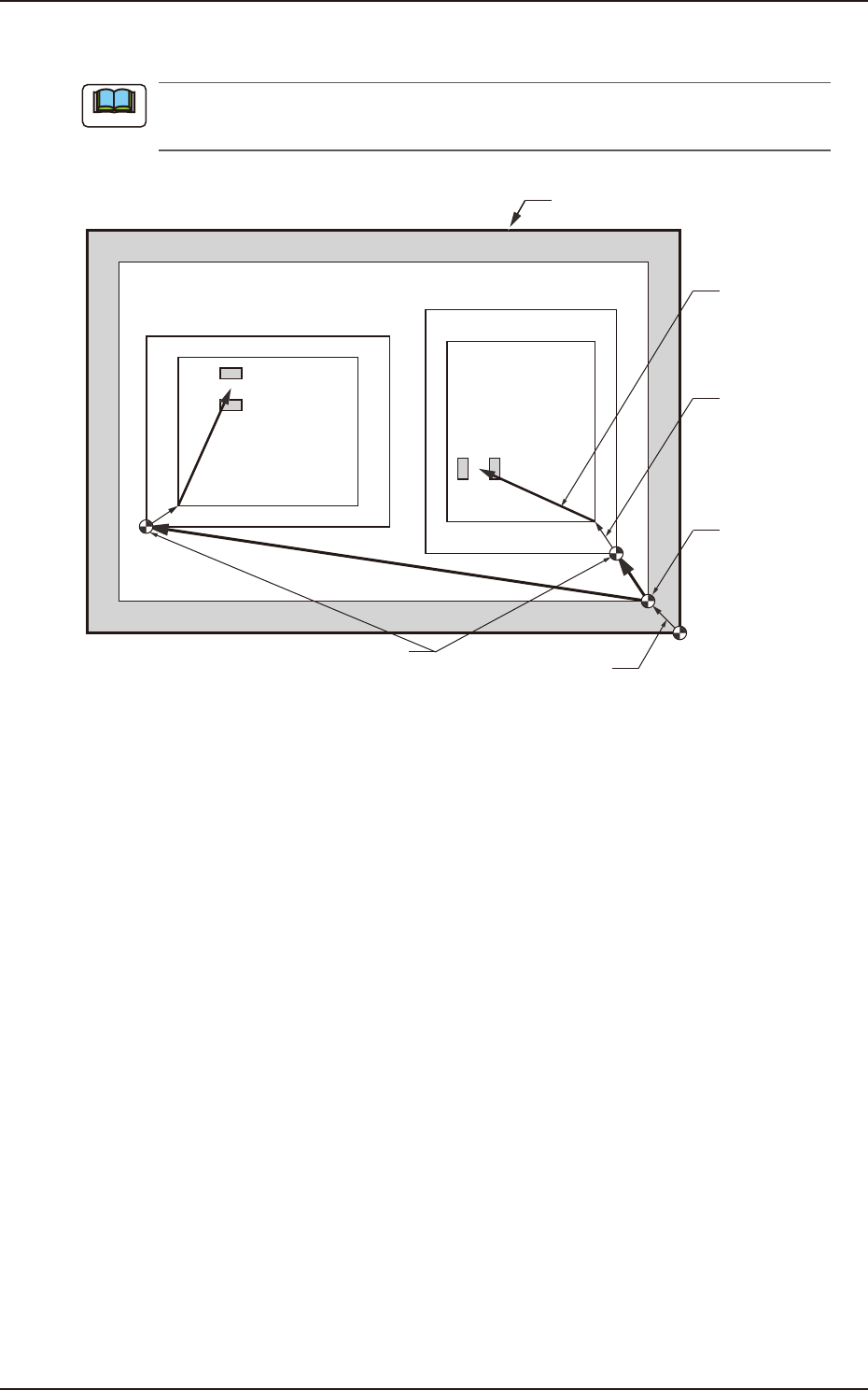
7.2.3 Placement Position Teach Operation Procedure
The following describes the procedure based on the assumption that "Front Right" is selected
as placement coordinate references. "Pn" and "On" are taught as follows.
Unit Pattern Angle : 270°
Unit Pattern Angle : 0°
Pn
Pn
PCB Outermost Shape
Placement
Position
O
2
O1
Placement Position
Reference
Pattern Origin
Unit Control
Offset
PCB Origin
PCB Origin Offset
F2F40
Note
EUKYX
6-35199-2100
7.2 "Place Pos Teach" Window
►
Automatic Teaching
• Data to be Taught
The following are data items to be taught.
• PCB Placement Position P1 to Pn Step (X, Y) on Placement Data (P).
• Pattern Origin O1 to On Coordinates (X, Y) on the placement Data (O).
►
Notes on Teaching Operation
When the PEC recognition is set to ON on the pattern program data, all the PEC recognition
processing should be completed before the placement position check in the placement position
teach operation. If the PEC recognition has been set to ON, when the teaching is started while the
machine is stopped, the PEC recognition will be performed at first.
(1) Select the pattern program (production model) to be taught and prepare for PCBs, etc.
(2) Select the "Cycle run" in the "Place Pos Teach" window and set the movement speed.
(3) To find the overall shifting tendency of the PCB patterns, press the [START] button on the
operation panel within 10 seconds after pressing the [Cycle run] button.
(4) Select the component outline and the condition of the pattern displayed while the X/Y
beam is working and select the step to be taught.
When the patterns of a certain step are specifically shifted to one side, it is required to teach
the P-data. When the overall patterns of a unit PCB are uniformly shifted to one side, the
O-data must be taught.
(5) Press the [Back] button. (Return to the "Place Pos Teach" window.)
See “7.2 “Place Pos Teach” Window” for the button positions.
Procedure
Note
Reference