EUKYX-199-2100_G5S2_Instruction_Vol2_E.pdf - 第265页
EUKYX 6-28 199-2100 7.1 "Fdr Pick-up T ch" Window (7) Press the [ ] but ton if ne ces sar y . (Che ck the n o z zle pick- up position) . F2F36 (8) When th e manual alignment op eration is comp lete d, press the…
EUKYX
6-27199-2100
7.1 "Fdr Pick-up Tch" Window
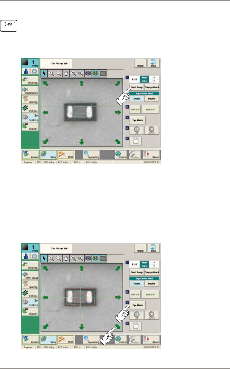
7.1.1 Fdr Pick-up Tch
(1) Press the [Head Sel] button on the “Fdr Pick-up Tch“ window.
(2) Press the [Block Sel] button.
(Select the appropriate block and select the tape feeder where the teaching is performed).
(3) Press the [Activate] button.
(The window is changed to the manual alignment window for the selected tape feeder.)
F2F34
(4) Press the [Send Comp] button. (Find the place necessary on the tape).
(5) When the manual alignment is not required :
Press the [Prev Fdr.] or [Next Fdr.] button to perform the manual alignment for the other
tape feeder.
When the manual alignment is required :
Follow the steps (6) and later.
(6) Press the [Eye Match] button.
(Start the manual alignment operation from the position shown using an arrow).
F2F35
Procedure
EUKYX
6-28199-2100
7.1 "Fdr Pick-up Tch" Window
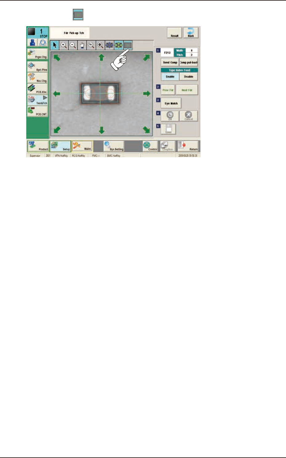
(7) Press the [
] button if necessary. (Check the nozzle pick-up position).
F2F36
(8) When the manual alignment operation is completed, press the [OK] button.
(In the case that the performed manual alignment is cancelled, press the [Cancel] button.)
(9) Press the [Save] button to save the manual alignment results.
EUKYX
6-29199-2100
7.2 "Place Pos Teach" Window
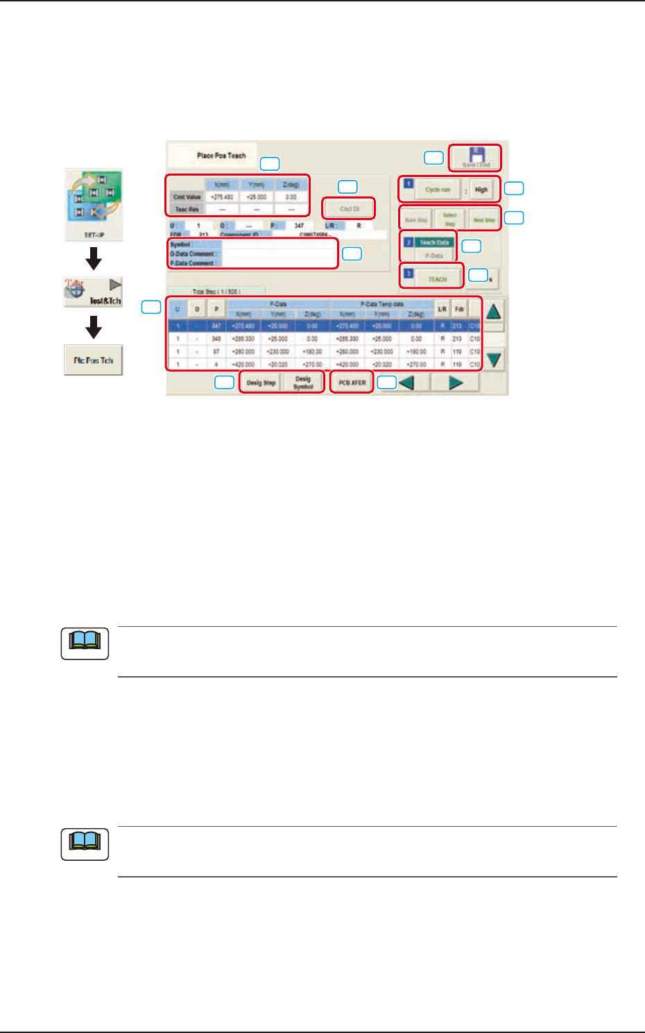
7.2 "Place Pos Teach" Window
Reflect the PCB pattern on the recognition area with the PCB recognition camera. Check if no
incorrect placement position specified by the pattern program is found. If the incorrect one is
found, revise the pattern program with the Eye match function (alignment of the component form
display and the PEC pattern).
[1]
[2]
[3]
[4]
[5]
[6]
[7]
[8]
[9]
[10]
[11]
Graphic
Development
F2F37
[1] "Step No."Display Section
The step data selected in the "Desig Step"(Designate Step) operation, is displayed.
[2] [Desig Step] and [Desig Symbol] Button
[Desig Step] Button
Using this button, the starting step No. is selected in the case that the placement position
teaching is started from any step No. in the pattern program.
The background color for the selected Step No., turns blue.
The serial setup of the "Starting Step No.", "U", "O", and "P" Nos. is available in the input
window displayed when the [Desig Step] button is pressed.
Normally, items are displayed in the order of component placement. However, pressing the [O]
or [P] button can arrange them in ascending order.
[Desig Symbol] Button
Using this button, the starting symbol name is selected in the case that the placement
position teaching is started from any symbol name in the pattern program. The background
color for the selected symbol turns blue.
The starting symbol name can be selected in the input window displayed when the [Desig
Symbol] button is pressed.
Normally, the items are displayed in the order of component placement. However, pressing the
[Desig Symbol] button can arrange them in ascending order.
Note
Note