EUKYX-199-2100_G5S2_Instruction_Vol2_E.pdf - 第114页
EUKYX 2-1 199-2100 1. Outline of Pattern Program 1 . Ou tli ne of P at tern P rogra m [1] [2] [3] [4] Graphic Development F2B1 [ 1 ] Patt ern Pro gram Menu The “Pa t tern Program Menu” window i s provided with the fol lo…

199-2100
Chapter 2
Pattern Program
This chapter describes of the pattern program.
1. Outline of Pattern Program
2. Composition of Pattern Program
3. Explanation of Pattern Program
EUKYX
EUKYX
2-1199-2100
1. Outline of Pattern Program
1. Outline of Pattern Program
[1]
[2]
[3]
[4]
Graphic
Development
F2B1
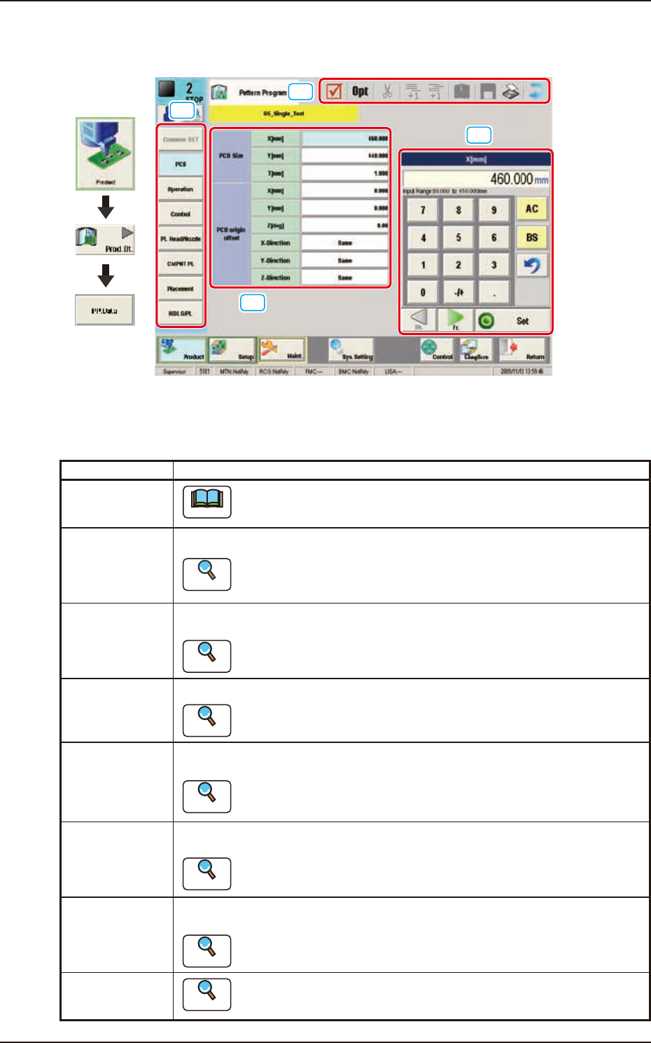
[1] Pattern Program Menu
The “Pattern Program Menu”window is provided with the following eight menu items. When each
button is pressed, the corresponding window appears.
Windows Description
Common SET
Note
This window is used for dual transfer (Option).
PCB Using these parameters, the PCB size and reference, etc. are set in this window.
Reference
Refer to”3.2 PCB” in this chapter for the details.
Operation Using these parameters, the PEC recognition mark used in the PEC recognition
operation, is set in this window.
Reference
Refer to “3.3 Operation” in this chapter for the details.
Control Using these parameters, the automatic operation is controlled.
Reference
Refer to “3.4 Control” in this chapter for the details.
PL Head/Nozzle Using these parameters, the nozzle is placed on the specified position (Placement
Nozzle/Head No.) in the head.
Reference
Refer to “3.5 PL Head/Nozzle” in this chapter for the details.
CMPNT PL Using these parameters, the component IDs (component types) to be arranged in
each fdr No. (Feeder No.), are set.
Reference
Refer to “3.6 CMPNT PL” in this chapter for the details.
Placement Using these parameters, the components in the component arrangement data are
set to place them on the specified coordinate position and in the specified direction.
Reference
Refer to “3.7 Placement” for the details.
HDLG/PL
Reference
Refer to “ 3. 8 H D LG / PL” in this chapter for the details.
EUKYX
2-2199-2100
1. Outline of Pattern Program
[2] Edited Data Display Area
The data items selected in the pattern program menu are displayed in this area.
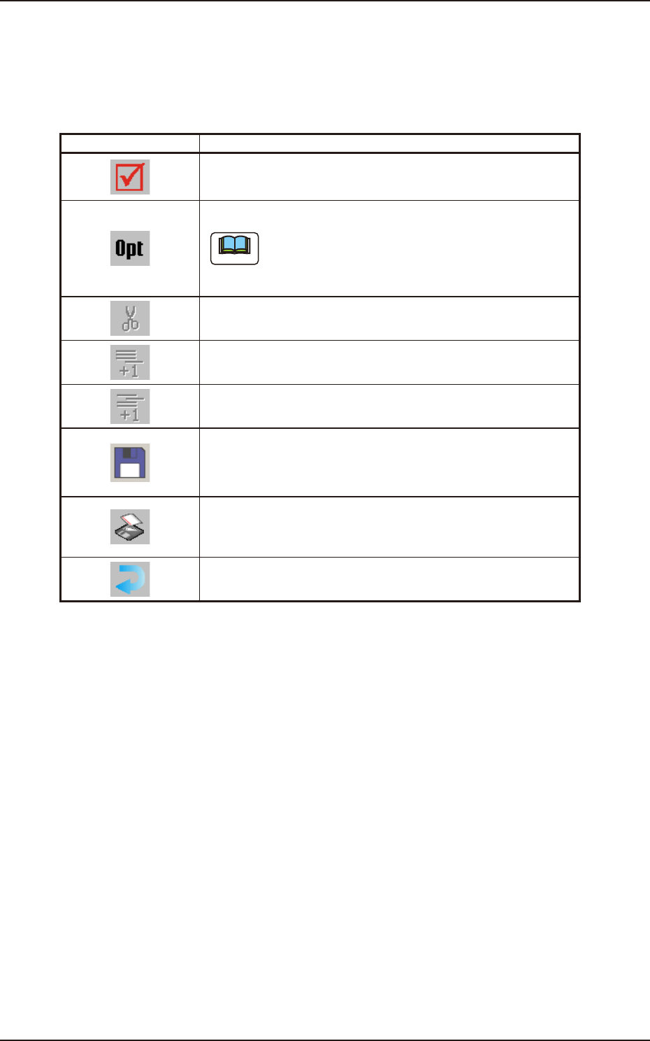
[3] Tool Bar
The operation commands that can be executed in the data edit window, are collectively displayed
as icons.
Icons Description
When selected, the data is checked.
Whether or not the data is completed, is checked.
When selected, the data is optimized.
Note
When pressed, the machine components are searched.
When selected, the data within the selectable range is cutout.
When selected, an empty line is added to the last portion.
An empty line is added to the last line.
When selected, an empty line is added to the cursor position.
An empty line is added to any position.
When selected the current file is saved.
The file currently in the course of editing, is saved.
In the case of new file, the file is to be saved with a new name.
When selected, the file is saved with a new name.
The file currently in the course of editing, is saved with a new
name.
When selected, the window is returned.
The "Product." window is returned.
[4] Data Edit Window
The ten-key pad or list selection buttons appropriate for the data selected in the pattern program
menu, are displayed in this window.
[AC] Button : When pressed, the data in the course of the entry operation, is cleared.
[BS] Button : When pressed, a backspace is given to the data in the course of the entry
operation.
[Bk.] Button
[Fr.] Button : When pressed, the displayed window is changed.
[Set] Button : When pressed, the entered numerical value or selected item is set.