EUKYX-199-2100_G5S2_Instruction_Vol2_E.pdf - 第165页
EUKYX 2-52 199-2100 3.7 Placement (G02 _04) Recog Coor d X 1 [mm ] and Recog Coo rd Y 1 [mm] Set the X1 a nd Y 1 coordi na tes of the first fiduci al mark based on the pat tern orig in. Recog Coor d X2 [mm] and Recog Coo…
EUKYX
2-51199-2100
3.7 Placement
(G02_02)
Offset
Offset X [mm] and Offset Y [mm]
Set the offset values for all placement coordinate X and Y in the placement data (P-data) and the
image and local PEC recognition coordinates.
(a) Use "+00.00" (zero) in normal cases.
(b) Note that these offsets are not reflected on "X [mm]" and "Y [mm]" in “(C01_02) All (Zones
1 through 5)”.
Offset Z [deg]
Set the offset value for all placement angles (Z=Theta) in the placement data (P-data).
Use "0.00" in normal cases.
Offset H [mm]
Set the offset value for all placement height "H" in the placement data (P-data).
In normal cases, set "+0.000" in this text box.
(G02_03)
Unit PCB Fiducial
Select one of the following options to determine whether or not the unit PCB BBR function should
be used.
Disable : The unit PCB BBR function is not used.
Enable : The unit PCB BBR function (2-point recognition) is used.
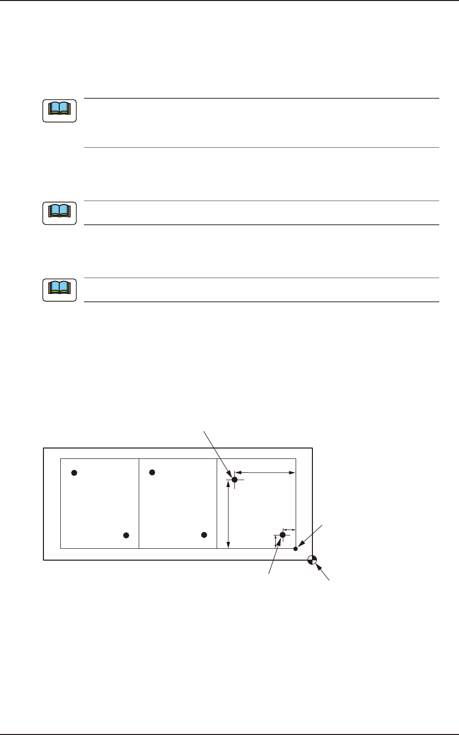
Y
1
X
2
Y
2
X
1
Second Fiducial Mark
Pattern Origin
First Fiducial Mark
Placement Coordinate
Reference
F2B47
Note
Note
Note
EUKYX
2-52199-2100
3.7 Placement
(G02_04)
Recog Coord X1 [mm] and Recog Coord Y1 [mm]
Set the X1 and Y1 coordinates of the first fiducial mark based on the pattern origin.
Recog Coord X2 [mm] and Recog Coord Y2 [mm]
Set the X2 and Y2 coordinates of the second fiducial mark based on the pattern origin.
(G02_05)
Fiducial Mark FM1 and Fiducial Mark FM2
Set the mark Nos. of the first and second fiducial marks FM1 and FM2. Select the mark Nos. (Mark
Codes) specified in the PEC recognition mark data of the operation data.
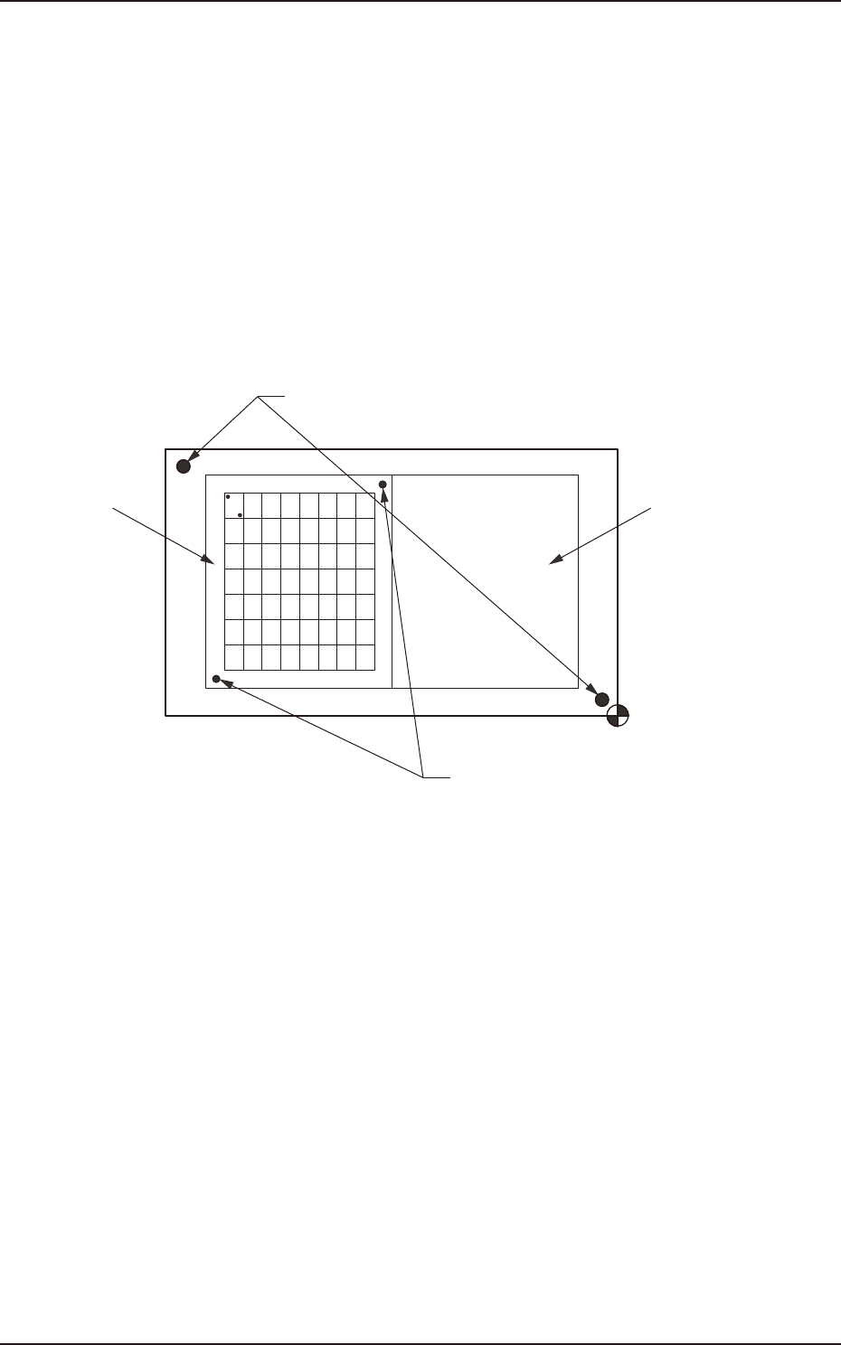
(G02_06)
Unit PCB Recognition
One to three points are setup for the PEC recognition for each U data.
U02
U01
Global Recognition
Unit PCB Recognition
F2A48
EUKYX
2-53199-2100
3.7 Placement
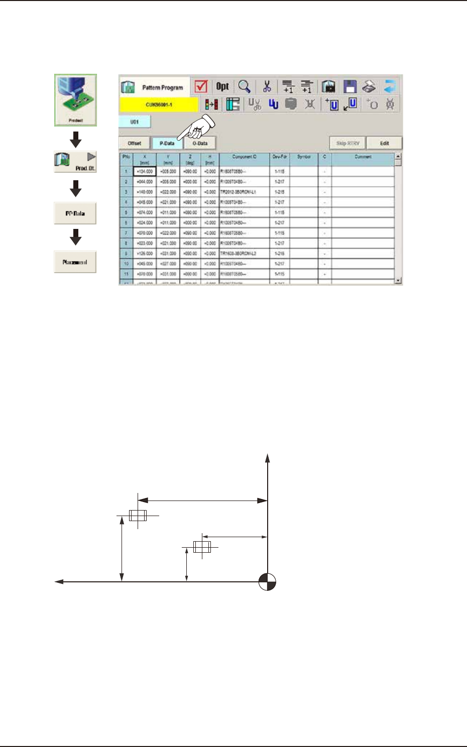
(G03) P-Data
When the [P-Data] button is pressed in the "Placement" window, the following tab sheet appears.
Graphic
Development
F2B49
(G03_01)
PNo
Shown are the step Nos. of the placement data (P).
Set coordinates and angles for component placement in the lines of the step Nos. (P-Nos.).
(G03_02)
X [mm] and Y [mm]
Set Coordinates X and Y for component placement. The coordinates must be based on the
placement coordinate reference (N0).
Y2
Y1
X1
X2
Y
X
Placement Coordinate Reference (No)
F2B50