EUKYX-199-2100_G5S2_Instruction_Vol2_E.pdf - 第296页
EUKYX 6-59 199-2100 7 .3. 7 "Create T each " Wiza rd Fol low the steps below to newl y create data to be taugh t. 7 . 3.7 . 1 L eade d Com pone nts - QFP ( 1 ) Sele ct [L eade d] - [IC ] - [QFP] on “ Create te …
EUKYX
6-58199-2100
[19] [20]
[18]
F2F64
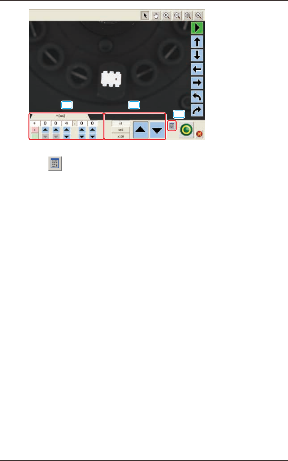
[18] [ ] Button
A ten-key pad appears for data entry.
[19] [increase / decrease] Button 1
Pressing the button for each unit directly increases or decreases the numerical value.
[20] [increase / decrease] Button 2
Selecting each unit of "× 1(0.01)" "× 10(0.1) and "× 100 (1)", increases or decreases the numerical
value in the selected units.
7.3 "COMP RCG" Test Window
EUKYX
6-59199-2100
7.3.7 "Create Teach" Wizard
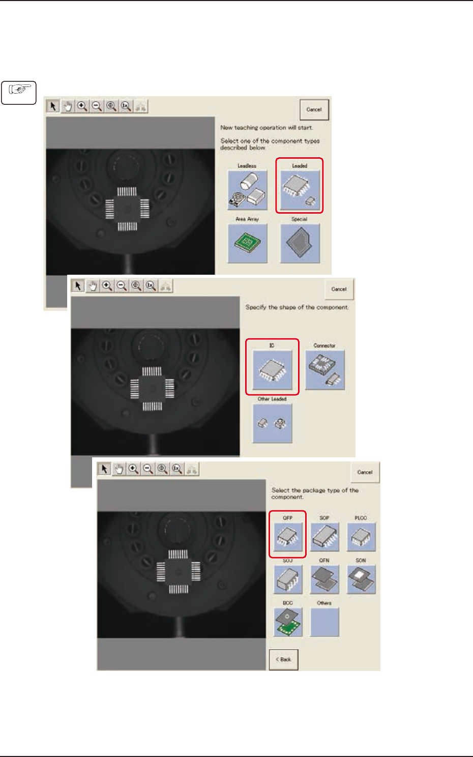
Follow the steps below to newly create data to be taught.
7.3.7.1 Leaded Components - QFP
(1) Select [Leaded] - [IC] - [QFP] on “Create teach wizard” window.
F2F65
Procedure
7.3 "COMP RCG" Test Window
EUKYX
6-60199-2100
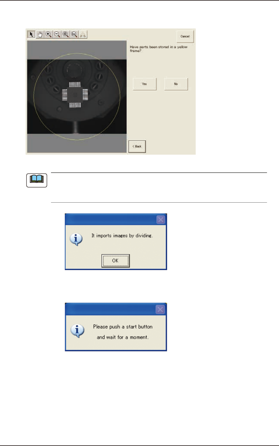
(2) Confirm that the component is in the yellow circle (frame).
When it is in the circle, press the [Yes] button. Otherwise, press the [No] button.
F2F68
When the [No] button is selected, the component image is split into several parts which are
subsequently captured and reassembled to create the whole image to be displayed.
The following dialog box appears. Press the [OK] button.
F2F69
When the [OK] button is pressed, the following dialog window opens. Press the [START] button on
the operation panel and wait until the divided image capturing is completed.
F2F70
Note
7.3 "COMP RCG" Test Window